




Abstract
Long-term online monitoring in extreme environments (e.g., high temperature, high pressure, liquid corrosion, strong electromagnetic radiation, confined narrow spaces, etc.) poses severe challenges to the stability and reliability of sensors. Optical fiber sensors, which employ optical signals as carriers, leverage inherent advantages such as immunity to electromagnetic interference, corrosion resistance, and electrical insulation, making them a critical technological route for extreme environment sensing. Among these, fiber-optic Fabry–Perot (F–P) sensors, operating by measuring changes in the interference cavity length, feature a simple structure, ease of miniaturization, high sensitivity, and high dynamic response. They are capable of detecting nanoscale displacement, vibration, and other minute signals and can be extended to measure multiple parameters (e.g., temperature, pressure, acceleration, etc.) via external sensitive structures. Consequently, they have become a research hotspot in high-precision optical fiber sensing. This paper systematically reviews fiber-optic F–P sensing technology. It first elaborates on the multi-beam interference mechanism and cavity length demodulation methods. It then analyzes the development history of sensing structure designs for physical quantities such as displacement, temperature, pressure, acceleration, and vibration, with particular emphasis on packaging techniques and demodulation strategies suitable for high temperature, high pressure, liquid media, and strong electromagnetic environments. This review introduces the engineering practices of such sensors in aerospace, oil and gas extraction, nuclear reactor monitoring, and other related fields. Finally, it discusses the progress in developing new-material optical fibers (e.g., sapphire fiber) and integrated probe assemblies suited for more extreme environments, such as those involving ultra-high temperature and strong irradiation. It explores the feasibility of applying artificial intelligence to adaptive decoupling under multi-field coupling, as well as miniaturized networking schemes based on integrated on-chip spectrometers. Furthermore, it envisions a trend toward the large-scale deployment of standardized and engineered measurement systems. This work provides a systematic reference for in-depth research and engineering applications of fiber-optic F-P sensing technology in extreme environments.
Keywords
fiber-optic fabry–perot (F–P) sensor; spectral demodulation; multi-field coupling; extreme environment; decoupling
1 Introduction
In practical engineering measurements, sensors that are long-term exposed to coupled extreme environments, such as high temperature, high pressure, corrosive liquid, strong electromagnetic interference, and intense radiation, while being required to operate stably in confined and narrow spaces, impose stringent demands on measurement stability, reliability, and long-term operational capability1–3. Conventional electrical sensors, which rely on metallic wires and electronic components, are prone to insulation degradation, electromagnetic induction noise, and other forms of signal crosstalk in high-temperature, humid, corrosive, and strong electromagnetic environments. In severe cases, these issues can lead to device burnout, making it difficult to meet the requirements of long-term online monitoring4–6. However, with the advancement of intelligent major equipment and extreme engineering environments, deep-earth energy extraction requires long-term in-situ monitoring of temperature, pressure, strain, vibration, and other parameters; deep-sea equipment demands stable operation under high hydrostatic pressure and strong corrosion; and nuclear power systems require high radiation resistance and high safety with long-term maintenance-free capability7–9. Therefore, the development of novel sensing technologies for extreme environments has become an important research direction in this field.
Compared with conventional electrical sensors, optical fiber sensors, which use optical signals as carriers, offer advantages such as immunity to electromagnetic interference and corrosion resistance, making them more suitable for extreme working conditions including high temperature, high pressure, liquid corrosion, and intense radiation10,11. According to their operating principles, optical fiber sensing technologies are mainly classified into two types: distributed and point-based. Distributed sensors are applicable to large-scale measurement scenarios such as bridge safety monitoring, whereas point-based sensors are more focused on local physical quantity detection12. Since their introduction, point-based optical fiber sensing technologies have evolved from intensity-based types toward interferometric and grating-based types capable of multi-parameter fusion sensing. Fiber Bragg gratings and fiber-optic Fabry–Perot (F–P) sensors have gradually become mainstream devices, collectively promoting the development of collaborative sensing of multiple parameters with high sensitivity and high stability13. As monitoring demand in increasingly complex environments grow, optical fiber sensing technology is transitioning from single-parameter measurement toward multi-parameter fusion for long-term online monitoring, thereby gradually establishing itself as a key technical approach for extreme environment sensing.
After years of development, point-based optical fiber sensing technologies have formed multiple technical routes, represented by F–P, fiber Bragg grating (FBG), fiber evanescent wave, and fiber surface plasmon resonance (SPR)14. Different sensing mechanisms and structural characteristics make them suitable for different application scenarios, collectively promoting the development of complex environment sensing. FBG sensors, by virtue of wavelength-encoded stability, immunity to light intensity fluctuations, and wavelength division multiplexing capability, are widely used in large-scale networked measurements. However, limited by the principle of refractive index modulation in the fiber core, their sensitivity is constrained by wavelength drift, resulting in relatively limited capability for detecting minute signals. Moreover, the decoupling of temperature and strain is complex15. Fiber evanescent wave sensors utilize the evanescent field that leaks into the cladding to sensitively detect changes in external refractive index and liquid media. Fiber SPR sensors further incorporate the surface plasmon resonance effect of metal thin films, exhibiting outstanding performance in chemical applications such as biomedicine, but they rely heavily on the external dielectric environment16–18. In contrast, fiber-optic F–P sensors operate based on changes in the interferometric cavity length, featuring a simple structure, ease of miniaturization, and both high sensitivity and high dynamic response. Their optical path length sensitive mechanism enables nanoscale monitoring of tiny displacement and vibration. Moreover, by introducing external sensitive structures, extrinsic sensors for temperature, pressure, acceleration, and other parameters can be constructed19,20. The four typical point-based optical fiber sensors mentioned above are shown in Fig. 1. Among them, the fiber-optic F–P sensor, by virtue of its unique interferometric measurement mechanism and excellent structural designability, has become a research hotspot in high-precision optical fiber sensing. The F–P sensor constructs a miniature optical resonant cavity to convert changes in external physical quantities into optical phase changes or interference spectral shifts, thereby enabling high-sensitivity detection of parameters such as temperature, pressure, strain, displacement, vibration, and acoustic signals (as illustrated in Fig. 2).
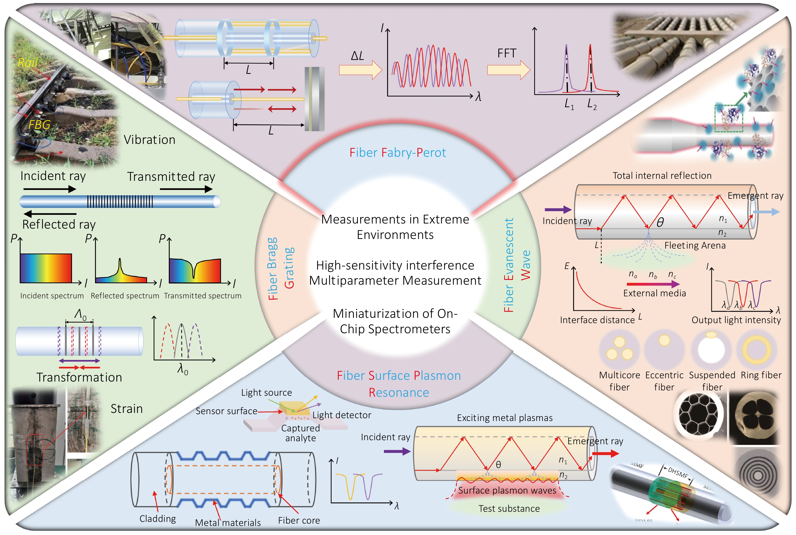
Figure 1. Main categories of fiber-optic point sensors.
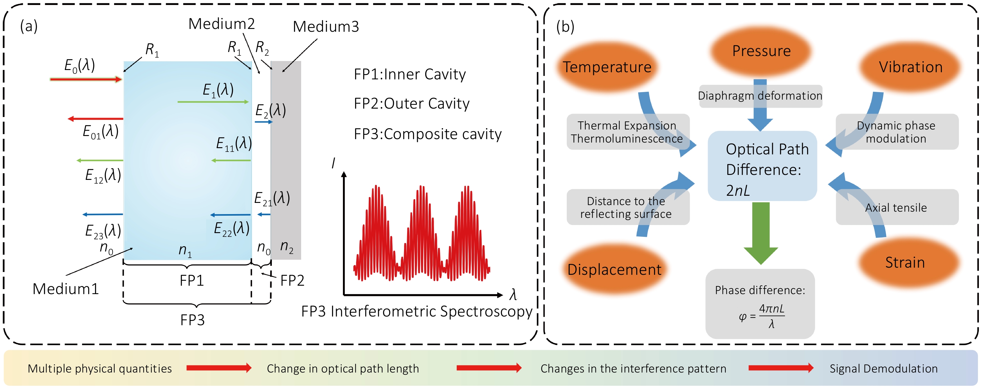
Figure 2. Sensing mechanism of fiber-optic F–P sensors. (a) Schematic of a composite F–P cavity consisting of the inner cavity FP1, outer cavity FP2, and composite cavity FP3. (b) Sensing mechanisms of the composite F–P cavity for different measurands, where n denotes the refractive index of the measurement environment.
Existing reviews have systematically surveyed fiber-optic Fabry–Perot sensing technologies from various perspectives. Islam et al. reviewed the development history, fabrication methods, operating principles, and applications of fiber-optic F–P sensors21 while Huang et al. focused on F–P interference models and different cavity configurations, summarizing their applications in refractive-index, temperature, and micro-displacement sensing22. As F–P sensors are increasingly extended toward extreme environments involving high temperature, high pressure, corrosive media, and intense radiation, research interests have broadened to include extreme-environment-resistant materials and packaging, multiphysics coupling, multiparameter decoupling, and high-precision intelligent demodulation. Accordingly, this review takes extreme-environment monitoring as its central theme and integrates sensing structures and materials, multiphysics coupling, multiparameter measurement, demodulation techniques, environmental adaptability, and engineering applications into a unified framework.
This paper presents a systematic review of fiber-optic F–P sensing technology. It begins by elucidating the core measurement mechanism and then traces the evolution of sensing structure designs for various physical quantities, including displacement, gap, temperature, pressure, acceleration, and vibration. Particular emphasis is placed on F–P sensing structures suited for complex environments characterized by high temperature, high pressure, liquid media, and strong electromagnetic fields. The paper systematically introduces packaging processes, demodulation techniques, and scenario-tailored engineering solutions. Furthermore, it discusses recent advances in the development of novel-material optical fibers and integrated probe assemblies for more extreme conditions, and evaluates the feasibility of multi-field coupled adaptive decoupling algorithms combined with artificial intelligence approaches, as well as miniaturized networking schemes based on integrated on-chip spectrometers. Finally, the paper outlooks the trend toward large-scale deployment of standardized and engineered measurement systems.
2 Core fundamental sensing mechanism and multi-field coupled response theory of fiber-optic F–P sensors
2.1 Fundamental theory of fiber-optic F–P interferometric sensing
Fiber-optic F–P sensors are typical interferometric fiber-optic sensors, and their core mechanism is based on multiple reflections and coherent superposition of light waves within an optical resonant cavity. Compared with intensity-modulated sensors, F–P sensors achieve physical quantity sensing by detecting optical phase changes, offering higher measurement resolution and sensitivity.
An F-P interference cavity consists of two parallel reflective surfaces that define an optical cavity of length L. Based on the structural configuration, the F–P cavity can be classified into two types: an intrinsic F–P interferometer (IFPI) and an extrinsic F–P interferometer (EFPI). The intrinsic type is formed directly within the optical fiber or through a sealed fabrication process, making it suitable for applications involving minute deformations induced by pressure, temperature, or other physical parameters. The extrinsic type creates an air cavity between the fiber end face and an external reflective surface, offering high structural flexibility and ease of packaging.
(1) Mechanism of F–P interference formation:
Let the incident electric field be:
\[{E}_{i}={E}_{0}{e}^{j\omega t}\;,\] (1)
where E0 is the amplitude of the incident light; ω is the angular frequency; t is time.
When the light wave reaches the first reflective surface, a portion of the light is reflected, generating the first reflected light beam E1. Another portion enters the F-P cavity, is reflected by the second reflective surface, and returns to form the second reflected light beam E2. The electric fields of the first and second reflected light beams are:
\[{E}_{1}={r}_{1}{E}_{0}{e}^{j\omega t} \;,\] (2)
\[{E}_{2}={t}_{1}{t}_{2}{r}_{2}{E}_{0}{e}^{j(\omega t+\phi )} \;,\] (3)
where r1 and r2 are the reflection coefficients; t1 and t2 are the transmission coefficients; Φ is the phase difference between the two beams.
Since the second reflected light beam propagates back and forth once inside the F-P cavity, the optical path difference between the two beams is:
\[\Delta =2nL\;,\] (4)
where n is the refractive index of the medium inside the cavity; L is the F-P cavity length.
The phase difference corresponding to the optical path difference is:
\[\phi=\frac{2\pi}{\lambda}\Delta=\frac{4\pi nL}{\lambda}\; .\] (5)
Due to the principle of interference superposition, the total output light intensity is:
\[I={\left| {E}_{1}+{E}_{2}\right| }^{2}={I}_{1}+{I}_{2}+2\sqrt{{I}_{1}{I}_{2}}\cos \phi \;,\] (6)
where I1=|E1|2, I2=|E2|2.
When Φ=2mπ, constructive interference occurs, and the output light intensity reaches its maximum. When Φ=(2m+1)π, destructive interference occurs, and the output light intensity is at its minimum. Therefore, the fiber-optic F-P sensor essentially achieves the sensing of external physical quantities by detecting the interference phase change.
(2) Multi-beam interference mechanism
For a high-reflectivity F–P cavity, multiple reflected beams are generated inside the cavity. In this case, the multi-beam interference model is adopted for analysis. Let the cavity surface reflectivity and transmissivity of each cavity surface be R and T, respectively. The transmitted light intensity follows the Airy distribution. The corresponding light intensities of the transmitted and reflected light are given by:
\[{I}_{t}={I}_{0}\frac{1}{1+F{\sin }^{2}(\phi /2)} \;,\] (7)
\[{I}_{r}={I}_{0}\frac{F{\sin }^{2}(\phi /2)}{1+F{\sin }^{2}(\phi /2)} \;,\] (8)
where F=4R/(1-R)2, which is the finesse coefficient.
As the reflectivity increases, the interference spectral linewidth decreases, the spectral peaks become sharper, the interference contrast improves, and the spectral resolution increases. Consequently, the measurement system exhibits more sensitive to both the stability of the light source and the influence of external mechanical vibrations.
(3) Modulation mechanism by external physical quantities
Fiber-optic F–P sensors belong to the category of optical path length modulated sensors. Their core measurement parameter is the optical path difference. External physical quantities change the interference phase by altering the cavity length L and the refractive index n. When small changes occur in the cavity length and refractive index, the corresponding phase changes are:
\[\Delta {\phi }_{L}=\frac{4\pi n}{\lambda }\Delta L \;,\] (9)
\[\Delta\phi_n=\frac{4\pi L}{\lambda}\Delta n\; .\] (10)
The total phase change is:
\[\Delta\phi=\frac{4\pi}{\lambda}(L\Delta n+n\Delta L)\; .\] (11)
Phase variation constitutes the theoretical basis for fiber-optic F-P sensors in sensing physical quantities such as temperature, pressure, strain, and vibration.
2.2 Common mechanism of multi-physical quantity cross-coupling interference in extreme environments
Fiber-optic F–P sensors achieve high-precision measurement based on optical phase changes and offer significant advantages under extreme operating conditions. However, their operating mechanism involves complex multi-field coupling problems. Multiple physical quantities such as temperature, pressure, strain, and vibration act simultaneously on the F–P cavity, causing coupled changes in cavity length L and refractive index n and producing cross-sensitivity. Factors such as sweep frequency nonlinearity, laser frequency jitter, packaging residual stress, and material thermal drift further degrade measurement stability and demodulation accuracy. Especially under high-temperature and high-dynamic conditions, multi-physical field coupling leads to interference spectrum broadening, spectral peak drift, and accumulation of frequency-domain demodulation errors. Essentially, any factor that alters either L or n induces a change in the interference phase. The strong nonlinearity and multi-scale characteristics of multi-physical quantity coupling in extreme environments constitute the core problem limiting measurement accuracy and stability. From the expression of total phase difference, nΔL represents the phase modulation due to cavity length change, and LΔn represents the phase modulation caused by refractive index change. Temperature, pressure, strain, vibration, material stress, and other factors all affect the F–P interference output by simultaneously modifying both L and n.
(1) Temperature cross-coupling mechanism
Temperature is the primary factor affecting the stability of fiber-optic F–P sensors. It induces cavity length changes via thermal expansion (as in Eq. (12)) and refractive index changes via the thermo-optic effect (as in Eq. (13)), thereby forming a dual modulation mechanism. The total optical path change is given by Eq. (14), and the corresponding wavelength shift by Eq. (15). Consequently, even during pressure or strain measurement, temperature variations introduce additional phase drift, resulting in temperature-induced cross-coupling. Under extreme high temperatures, parameters such as the coefficient of thermal expansion, refractive index, elastic modulus of packaging materials, and interfacial thermal stress exhibit nonlinear changes, leading to nonlinear drift of the interference spectrum and increased zero-point drift.
\[\Delta L=\alpha L\Delta T\;,\] (12)
\[\Delta n=\xi n\Delta T\;,\] (13)
\[\Delta (OPD)=2(n\Delta L+L\Delta n) \;,\] (14)
\[\Delta\lambda=(\alpha+\xi)\Delta T\; .\] (15)
(2) Pressure and stress coupling mechanism
A diaphragm-type fiber-optic F–P pressure sensor relies on the flexural deformation of the diaphragm to change the cavity length. The cavity length change equals the central displacement of the diaphragm, satisfying Eq. (16) under small deformation. When temperature rises, Young's modulus decreases, the diaphragm stiffness decreases, and the pressure sensitivity changes accordingly, forming temperature-pressure coupling.
\[\delta \propto \frac{P{a}^{4}}{E{h}^{3}} \;,\] (16)
where P is the pressure; a is the diaphragm radius; h is the diaphragm thickness; E is Young's modulus.
(3) Vibration and dynamic phase disturbance mechanism
Vibration induces periodic changes in the cavity length (as in Eq. (17)), which correspond to dynamic phase modulation (as in Eq. (18)). Simultaneously, it may cause interference frequency shift, fiber bending loss, cavity surface tilt, and degradation of interference contrast.
\[L(t)={L}_{0}+\Delta L\sin ({\omega }_{v}t)\;,\] (17)
\[\phi(t)=\frac{4\pi n}{\lambda}[L_0+\Delta L\sin(\omega_vt)]\; .\] (18)
Based on the above mechanisms, the interference phase change of fiber-optic F–P sensors in extreme environments results from the combined effects of multiple physical fields. The system output can be expressed as Eq. (19). Nonlinear coupling exists among the physical quantities. Traditional single-parameter calibration methods are insufficient to meet the demands of high-precision measurement. Therefore, it is necessary to suppress cross-interference through either multi-cavity structure decoupling or multi-physical field joint modeling.
\[\Delta\phi=\Delta\phi_T+\Delta\phi_P+\Delta\phi_{\varepsilon}+\Delta\phi_v+\Delta\phi_n\; .\] (19)
The models described above capture the common coupling mechanisms through which multiple physical fields act on the F-P cavity. However, the actual degree of coupling is highly dependent on sensor material, cavity dimensions, sensing structure, and operating conditions, and thus cannot be characterized by a single unified coefficient. Consequently, multiparameter coupling should generally be evaluated on a case-by-case basis for specific application scenarios, using quantitative indicators such as cross-sensitivity and residual measurement error after decoupling. For instance, in combined temperature–pressure measurements, the pressure–temperature cross-sensitivity can be employed to quantify the equivalent pressure error induced by temperature variations. A value as low as 5.96 Pa/°C has been reported for an all-silicon dual-cavity F–P sensor61. For an F-P sensor that incorporates an independent temperature-compensation channel, the pressure measurement accuracy after compensation reached 0.52 %FS, providing another quantitative metric for assessing decoupling performance56.
3 Chipization of sensitive structures, structurization of sensing chips, and metallization packaging of fiber-optic F–P sensors
3.1 Overview of measurable physical quantities and classification of fiber-optic F–P sensors
In recent years, the application scope of fiber-optic F–P sensors has expanded from traditional mechanical parameters to areas such as environmental sensing, field detection, and functional micro-devices. Driven by optical microcavities and high-sensitivity interferometric readout techniques, they have gradually become suitable for weak signal and complex scenario detection23,24. Concurrently, the integration of F–P interference structures with specialty optical fibers, microcavities, and functional materials has promoted structural diversification in medium sensing and multi-physical quantity detection25,26. Furthermore, the development of three-dimensional micro-structuring on fiber end faces and micro-packaging techniques has further advanced the evolution of sensors from single-cavity structures toward miniaturized, integrated, and functional devices27,28.
Given the differences in action mechanisms, sensing principles, and application environments among various physical quantities, this paper categorizes representative works into two classes: mechanical parameter detection and environment/field interaction parameter detection29–33. Their applications in structural deformation sensing, dynamic load measurement, functional material coupling, and complex environment monitoring are discussed separately. Combined with the related work of our research group, the research ideas toward multi-parameter synchronous measurement, chip-based design, and metallization packaging are outlined.
3.2 Fiber-optic F–P sensors for typical mechanical parameters
Detection of mechanical parameters represents an important application direction of fiber-optic F–P sensors, with related research mainly focusing on force, displacement, vibration, pressure, and strain. As shown in Fig. 3, owing to the distinct forms of action and structural response modes associated with different mechanical parameters, existing works have established multiple implementation paths in terms of sensitive structure design, cavity configuration, fabrication processes, and signal demodulation methods.
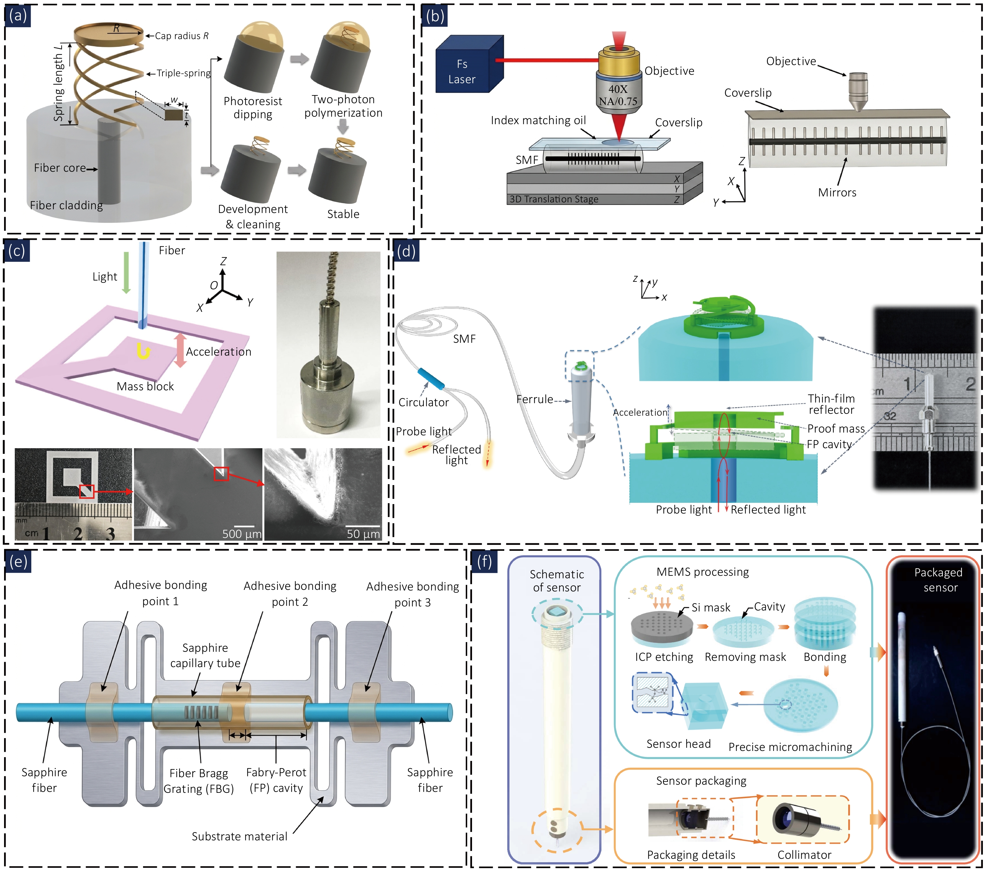
Figure 3. (a) 3D spring-based fiber-tip F–P micro-force sensor. (b) Cascaded F–P fiber strain sensor based on the comb-spectrum Vernier effect. (c) Sapphire-diaphragm fiber-optic F–P vibration sensor. (d) In situ 3D-printed fiber-tip F–P micro-interferometric accelerometer. (e) Cascaded sapphire-fiber F-P/FBG strain sensor for high-temperature strain measurement. (f) Temperature-compensated sapphire MEMS F–P pressure sensor. Fig. reproduced from: (a) ref.34, John Wiley and Sons; (b) ref.40, IEEE; (c) ref.36, American Chemical Society; (d) ref.37, Light Publishing Group; (e) ref.41, Elsevier; (f) ref.39, Optica Publishing Group.
For micro-force measurement, Shang et al. (2024)34 fabricated a three-dimensional spring-integrated F–P microcavity on the fiber end face using two-photon polymerization, and realized force detection based on cavity length change caused by spring compression. Experimental results show that the sensor has a force sensitivity of 0.436 ± 0.007 nm/nN, a resolution of 40.0 ± 0.7 pN, and a detection range of 34.8 nN.
For displacement measurement, Li et al. (2024)35 proposed an ethanol-filled fiber microcavity displacement sensor. They utilized lateral 1550 nm laser-induced Marangoni effect to drive microbubble movement, and demodulation was achieved through optical path length change of the F-P cavity. The spatial frequency demodulation sensitivity in the range of 0–2550 μm is 0.00115 nm−1/μm, the small-range wavelength demodulation sensitivity is 6.91 nm/μm, and the resolution is approximately 6 nm.
Vibration and acceleration detection typically require combining an inertial proof mass, diaphragm, or micro-beam structure with the F–P cavity to convert external dynamic loads into cavity length changes. Cao et al. (2024)36 constructed a high-temperature fiber-optic F–P vibration sensor using a sapphire sensitive diaphragm. The sensor can operate at 600 °C, with a room temperature sensitivity of 38.66 nm/g, a characteristic frequency of 2446 Hz, and a transverse response ratio of 4.09%. Wang et al. (2025)37 fabricated an F–P micro-interferometric acceleration sensor integrating a proof mass, reflective film, and supporting micro-beams on the end face of a ferrule by in-situ three-dimensional micro-printing. The sensor exhibits a linear response in the range of 0–10 g, a flat response bandwidth of 2–3 kHz, and a noise-equivalent acceleration of 62.45 μg/√Hz.
For pressure measurement, fiber-optic F–P sensors typically convert pressure into cavity length changes using elastic diaphragms, polymer spacer layers, or high-temperature resistant cavities. Zhen et al. (2023)38 constructed a fiber end-face F-P pressure sensor using an atomically smooth gold micro-sheet and a PDMS spacer layer. The device with a PDMS clamped beam shows a sensitivity of 11.48 nm/kPa in the range of 0–2.34 kPa, with a pressure resolution of approximately 1.73 Pa. Liao et al. (2025)39 fabricated a temperature-compensated fiber-optic F-P pressure sensor based on sapphire MEMS technology and direct bonding technology, capable of measuring temperature and pressure in the ranges of 25–1500 °C and 0–1 MPa. The pressure sensitivity is 0.782–0.952 μm/MPa, and the pressure measurement accuracy after compensation is 0.86% F.S.
For strain detection, cascaded F–P cavities, the Vernier effect, and temperature compensation structures are used to improve demodulation sensitivity or reduce thermal cross-sensitivity. Wei et al. (2024)40 proposed a cascaded F–P cavity fiber-optic sensing structure based on the comb-spectrum Vernier effect to achieve strain and temperature demodulation. The strain and temperature sensitivities reach 4.76 pm/με and 271.61 pm/°C, respectively, which are approximately 21.6 times and 23.16 times higher than those of a single-stage cascaded F–P cavity. Shen et al. (2025)41 integrated a cascaded F–P cavity and a fiber Bragg grating into a sapphire fiber to achieve temperature-compensated strain measurement up to 1150 °C within a range of ±1000 με. The maximum measurement errors at room temperature and 1150 °C do not exceed 5% and 14%, respectively.
Overall, research on fiber-optic F–P sensors for typical mechanical parameters mainly focuses on the construction of micro-structured sensitive elements, the regulation of cavity response, and demodulation compensation under complex environmental conditions. The related work lay a foundation for subsequent sensor structural integration, multi-parameter measurement, and engineering packaging.
3.3 Fiber-optic F–P sensors for environment and field interaction parameters
With the development of sensitive materials, micro/nano fabrication, and end-face integration technologies, fiber-optic F–P sensors have expanded from typical mechanical parameter detection to environment and field interaction parameters, including acoustic waves, gases, magnetic fields, temperature, and humidity. As illustrated in Fig. 4, such sensors typically rely on acoustic-sensitive diaphragms, photothermal effects, magnetically sensitive units, thermally sensitive cavities, or hygroscopic materials for signal transduction. Their structural design increasingly depends on the compatibility between functional materials and microstructures. Among these, acoustic detection represents one of the key application directions of fiber-optic F–P sensors. Wang et al. (2025)42 fabricated a hollow F–P ultrasonic sensing structure on the fiber end face by two-photon polymerization and metal evaporation, and used it for photoacoustic imaging detection. The sensor exhibits an acoustic pressure sensitivity of 797 mV/kPa, a noise-equivalent pressure of 2.8 Pa, a center response frequency of 1.5 MHz, and a bandwidth of 1.2 MHz. Different from ultrasonic detection, Wang et al. (2024)8 proposed a miniature fiber-optic F–P acoustic sensor for mHz-level infrasound signals, which has a flat response in the range of 0.01–2500 Hz, an acoustic pressure sensitivity of −123.19 dB re 1 rad/μPa at 5 Hz, and a minimum detectable pressure of 1.2 mPa/√Hz.
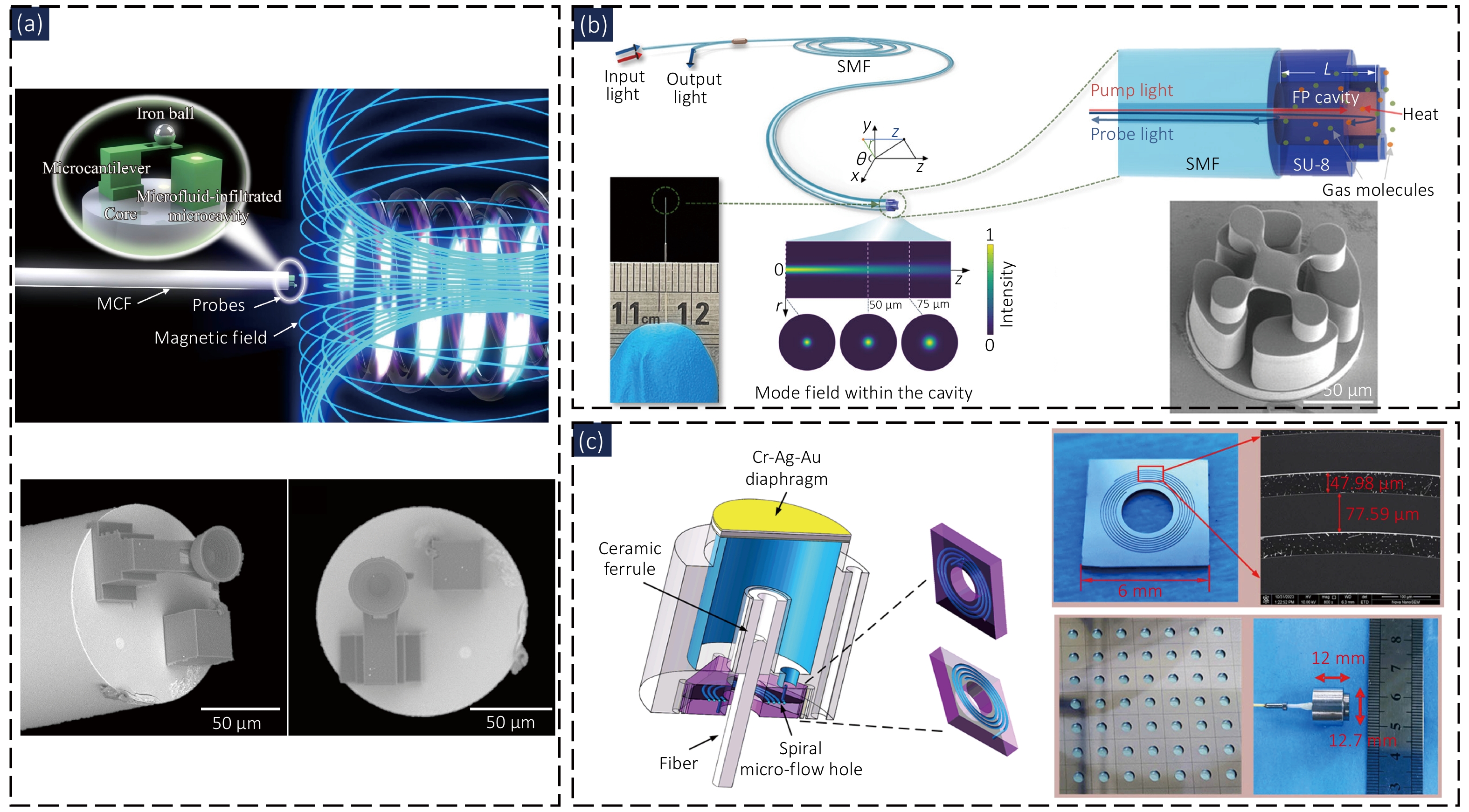
Figure 4. (a) 3D-printed multicore fiber-tip F–P sensor for discriminative magnetic field and temperature measurements. (b) Fiber-tip 3D-microprinted F–P photothermal interferometric gas sensor. (c) Miniaturized fiber-optic F–P sensor for mHz infrasound detection. Figure reproduced from: (a) ref.45, Light Publishing Group; (b) ref.43, John Wiley and Sons; (c) ref.8, Optica Publishing Group/Chinese Laser Press.
Gas detection, in contrast, relies more heavily on photothermal effects, absorption spectra, and gas-cavity interaction within microcavities. Zhao et al. (2024)43 fabricated a low-finesse F–P microcavity on the end face of a single-mode fiber by three-dimensional micro-printing and realized C2H2 detection based on the photothermal interference mechanism. The cavity length is approximately 66 μm, the noise-equivalent concentration is 160 ppb, the response time is less than 0.5 s, and the signal fluctuation over 25 h is approximately ±1.5%. Zhao et al. (2026)44 introduced the mode Vernier effect to construct a short-cavity F–P photothermal detection unit, achieving C2H2 detection in a 1 mm cavity length and 0.8 nL hollow-core gas cell. The lowest detection limit is 12 ppb, the noise-equivalent concentration is 75 ppb, and the response time is approximately 3 s.
Magnetic field and temperature detection are often challenged by temperature-induced cross-sensitivity and the need for multi-parameter decoupling. Consequently, recent studies have employed multi-channel structures on multi-core fiber end faces to achieve discriminative measurement. Xiong et al. (2024)45 fabricated dual F–P microcavities on the end face of a multi-core fiber using two-photon polymerization to achieve magnetic field and temperature measurement. The maximum magnetic field sensitivity is 1805.6 pm/mT, the response time is approximately 213 ms, and the temperature sensitivity is 160.3 pm/°C. For simultaneous temperature and pressure measurement, Chen et al. (2024)46 fabricated an open F–P microcavity by femtosecond laser two-photon 3D printing, and compensated for temperature crosstalk using an in-fiber FBG to achieve simultaneous measurement of temperature and pressure. The pressure sensitivity is 6.6649 nm/MPa, and the temperature sensitivities of the F-P microcavity and FBG are 0.105 nm/°C and 9.5 pm/°C, respectively.
For humidity detection, the adsorption, swelling, and mass loading changes of the sensitive film directly affect the sensor output. Li et al. (2026)47 constructed a Ti3C2Tₓ MXene-GO composite film fiber-optic F–P resonant humidity sensor, achieving humidity detection through photothermal excitation and non-contact interferometric readout. In the range of 2–100%RH, the absolute sensitivity and relative sensitivity are 2.1 kHz/%RH and 0.22%/%RH, respectively, and the response/recovery time is 3.61/5.53 s.
These findings indicate that the development of fiber-optic F–P sensors for environmental and field interaction parameters not only expands the range of measurands but also drives structural evolution toward configurations based on sensitive diaphragms, photothermal microcavities, functional materials, and resonant units. Compared with sensors designed for typical mechanical parameters, such devices are more susceptible to material response, environmental disturbances, and cross-sensitivity, requiring further improvements in structural stability, decoupling capability, and packaging adaptability.
3.4 Fiber-optic F–P sensors for multi-parameter synchronous testing
In extreme environments such as nuclear energy facilities, aero-engines, and high-temperature fluid equipment, measurement of a single physical quantity often fails to meet the requirements of practical condition monitoring12. Fiber-optic F–P sensors offer advantages such as small size, immunity to electromagnetic interference, long-distance transmission capability, and ease of integration with high-temperature resistant materials and metal packaging structures, rendering them well suitable in high-temperature, high-pressure, highly corrosive, and confined installation spaces48–51. Temperature, pressure, strain, displacement, and vibration often act simultaneously on the sensor structure and introduce strong thermal drift, packaging stress, and cross-sensitivity. Consequently, compared with the aforementioned single-parameter fiber-optic F–P sensors, engineering applications in extreme environments place greater emphasis on long-term stability of the sensor under complex service conditions, while requiring in-situ temperature information during the measurement of the target parameter, and achieving temperature compensation through structural design and demodulation algorithms. As shown in Fig. 5, to address this issue, our group has carried out a series of studies ranging from single-parameter adaptation to extreme environments to composite-cavity multi-parameter synchronous measurement. This work has led to a design approach for fiber-optic F–P sensors characterized mainly by chipization of sensitive structures, structurization of sensing chips, and all-metal packaging.
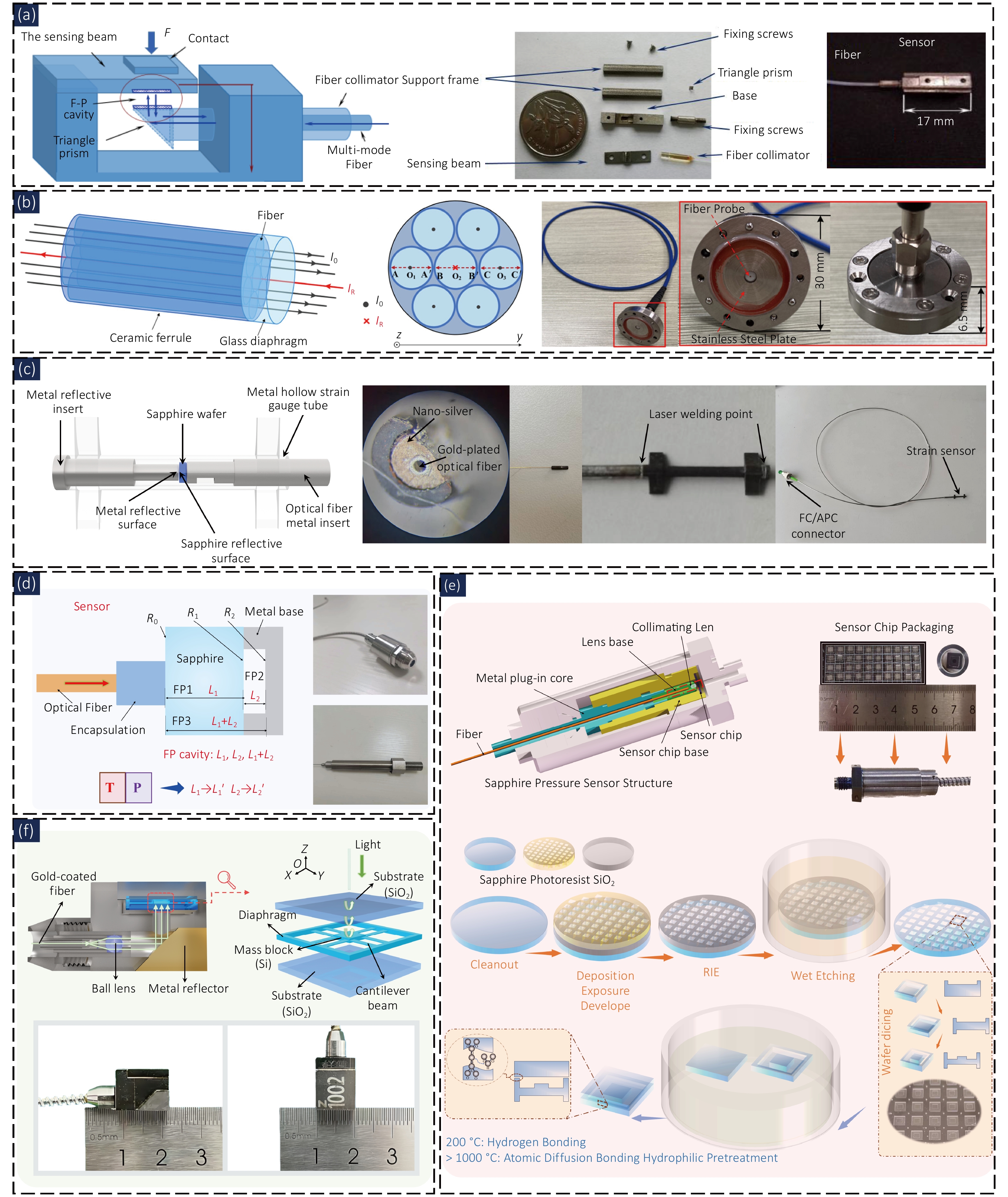
Figure 5. (a) Miniaturized fiber-optic F–P force sensor for radial impact force measurement. (b) Miniaturized fiber-optic F–P displacement sensor for fuel-pin vibration monitoring. (c) All-metal packaged temperature-compensated fiber-optic F–P strain sensor for high-temperature liquid-metal environments. (d) Dual-function composite-cavity fiber-optic F–P sensor for simultaneous pressure and temperature measurement. (e) All-sapphire composite-cavity fiber-optic F–P pressure sensor system with in situ temperature compensation. (f) Composite-cavity fiber-optic F–P interferometric accelerometer with temperature calibration for high-temperature and high-pressure applications. Figure reproduced from: (a) ref.52, MDPI; (b) ref.53, John Wiley and Sons; (c) ref.55, Elsevier; (d) ref.56, IEEE; (e) ref.57, Springer Nature; (f) ref.58, Springer Nature.
Early work mainly focused on the measurement of mechanical parameters in nuclear power equipment under confined spaces, high temperature, high pressure, and humid/hot environments. We (2017)52 designed a miniaturized fiber-optic F–P force sensor for detecting radial collision force between steam generator heat transfer tubes and support plates. The packaged sensor dimensions were 17 mm × 5 mm × 3 mm, and it was tested under humid/hot conditions, high pressure of 10 MPa, high temperature of 350 °C, and vibration environment of 40 kHz. Subsequently, the sensor was installed in a 1:1 steam generator test loop to acquire radial collision force signals. This work focused more on the design of force sensing structures in confined spaces and high-temperature high-pressure packaging adaptation, laying a foundation for subsequent engineering applications of fiber-optic F–P devices in nuclear power scenarios.
For monitoring fuel rod vibration displacement, we (2024)53 designed a cylindrically packaged fiber-optic F–P displacement sensor with an overall device size of 30 mm × 6.5 mm. The F–P cavity was formed jointly by a sapphire glass sheet and the surface of the fuel rod under test. Experimental results show that the displacement measurement range of the sensor in a wet environment is approximately 1250 μm, and the RMSE in wet environment and at 350 °C high temperature are about 0.112 and 0.144, respectively, indicating that such sensors have begun to shift from simple structural feasibility verification to measurement stability verification under real service environments.
For strain detection of fuel assemblies, we (2022)54 proposed a fiber-optic F–P strain sensing system based on non-scanning correlation demodulation and designed a dual-elastic-ring structure to transfer the strain on the fuel plate surface to the F–P cavity length change. Experimental results show that the strain sensitivity of the system at 300 °C reaches 12.6 nm/με, with a dynamic test frequency range of 10–500 Hz. In thermal-hydraulic experiments under high temperature, high pressure, and high-speed water flow scouring, the consistency deviation of the measurement data was less than 1.5%.
Building on this foundation, the research group further shifted its focus to composite cavity structures and temperature compensation methods. We (2025)55 proposed an all-metal packaged temperature-compensated fiber-optic F–P strain sensor for surface strain monitoring in a liquid metal environment at 500 °C and 2 MPa. A composite cavity structure, consisting of a metal hollow strain tube, a metal ferrule, and a sapphire substrate was employed to achieve strain measurement and in-situ temperature monitoring. The sensor uses 316L stainless steel as the packaging material, combined with nano-silver low-temperature sintering and laser welding processes to achieve high-temperature sealing. A strain sensitivity of 2.43 nm/με was obtained in a liquid metal environment at 500 °C, and the cavity length vibration remained below 8 nm over a 60-hour high-temperature and high-pressure stability test.
Simultaneous measurement of pressure and temperature is a typical application direction of composite-cavity fiber-optic F–P sensors. We (2025)56 designed an integrated temperature-pressure composite-cavity fiber-optic F–P sensor, in which a substrate cavity and an air cavity carry temperature and pressure information respectively, and fast dual-cavity decoupling was achieved through dedicated spectrometer hardware design and spectral region separation. In experiments, the sensor achieved simultaneous temperature and pressure measurement in the ranges of 0–500 °C and 0–4 MPa, with a temperature measurement accuracy of 0.35%FS and a pressure measurement accuracy after temperature compensation of 0.52%FS.
For pressure measurement under even more extreme temperature conditions, we (2026)57 further proposed an all-sapphire composite-cavity fiber-optic F–P high-temperature pressure sensing system. The sensing chip adopts a dual-cavity structure consisting of a sapphire substrate cavity and an air pressure cavity, and a pressure-sensitive diaphragm with a central platform is used to improve the reflection spectrum quality. In terms of fabrication, the system combines MEMS wet etching, RIE hard mask preparation, and high-temperature wafer-level bonding to achieve sapphire sensitive chip processing. Meanwhile, the APSC-FFT algorithm is proposed for cavity length demodulation. Experimental results show that the system can operate in the ranges of 28–800 °C and 0–1.2 MPa, with temperature and pressure system errors better than 0.13%FS and 0.18%FS, respectively, and pressure stability better than 0.12%FS. The unpackaged chip retains a measurable signal after long-term annealing at 1500 °C.
In addition to static pressure and strain measurement, composite cavity structures have also been employed for dynamic acceleration sensing. We (2026)58 proposed a composite-cavity fiber-optic F–P acceleration sensor with temperature calibration function for monitoring flow-induced vibration of steam generator heat transfer tubes in pressurized water reactors. In this sensor, a glass substrate cavity is used for temperature measurement, and an air cavity is used for acceleration response. The sensing chip adopts a three-layer structure consisting of a silicon diaphragm and a glass substrate, and chip fabrication and high-temperature sealing are achieved through wet etching, silicon-glass bonding, and laser welding. Experimental results show that the sensor exhibits a room temperature sensitivity of 4.53 nm/g, a resonant frequency of 7450 Hz, a minimum transverse sensitivity of 0.281%, and a cavity length drift of less than 0.1 nm during a 60-hour continuous test at 350 °C and 17.5 MPa.
The foregoing work demonstrates that the research group’s contributions extend beyond the mere deployment of fiber-optic F–P sensors for the detection of diverse physical quantities. Instead, they systematically address common challenges inherent to extreme-environment measurements, including temperature crosstalk, cavity length drift, structural reliability, and packaging adaptability. Early force and displacement sensors mainly solved the problems of structural miniaturization and engineering installation under high-temperature, high-pressure, humid/hot environments. Subsequent strain, pressure, and acceleration sensors further introduced composite cavity structures, employing an air cavity for target parameter measurement and a substrate cavity for in-situ temperature characterization. Through spectral separation, FFT demodulation, temperature calibration models, and all-metal packaging, these sensors have achieved improved measurement stability in complex environments. Overall, this line of work reflects the technical path of fiber-optic F–P sensors evolving from single sensitive cavities to composite cavities, multi-parameter synchronous measurement, and extreme-environment packaged devices, and also provides a foundation in structural design and fabrication processes for subsequent multi-physics collaborative sensing in high-temperature high-pressure environments.
To further illustrate the application characteristics of composite cavity structures in multi-parameter measurement in extreme environments, this paper selects representative F-P sensors for high-temperature strain, pressure/temperature synchronous measurement, and acceleration detection for comparison59–63, as shown in Table 1. Since the sensitivity units and evaluation indicators corresponding to different measurement objects are not consistent, simply comparing sensitivity magnitudes cannot fully reflect sensor performance. Therefore, the table mainly summarizes the working conditions, key performance, temperature compensation methods, and packaging adaptability of the sensors.
Table 1. Comparison of representative F–P sensors for multiparameter sensing in extreme environments.
| Measurand | Ref. | Configuration | Operating conditions | Key performance | Compensation/package |
| Strain | ref.59 | Dual FPIs + FBG | 900 °C | 178.75 pm/με | FBG compensation; no special package |
| Strain | ref.41 | Sapphire F–P + FBG | 1150 °C | 21.7 nm/με; max. error 14% at 1150 °C | FBG compensation; three-point bonding |
| Strain | ref.60 | ARHCF F–P | 1000 °C | 2.05 pm/με | No compensation; miniature reflective probe |
| Strain | ref.55 | Sapphire-metal composite F–P | 500 °C, 2 MPa | 2.43 nm/με; cavity drift <8 nm/60 h | Self-compensation + calibration; all-metal package |
| Pressure/ temperature | ref.61 | All-silicon dual-cavity F–P | T: 0–700 °C; P: 0.02–0.28 MPa | T: 0.53%FS; P: 1.70%FS | Dual-cavity demodulation; Si-Si bonding/ceramic adhesive; |
| Pressure/ temperature | ref.62 | All-sapphire dual-cavity F–P | T: 0–1400 °C; P: 0–5 MPa | T: 0.85%FS; P: 1.80%FS | Dual-cavity temperature compensation; high-temperature adhesive bonding |
| Pressure/ temperature | ref.56 | Sapphire-metal composite F–P | T: 0–500 °C; P: 0–4 MPa | T: 0.35%FS; P: 0.52%FS | In situ temperature compensation; metal-packaged sensing head |
| Pressure/ temperature | ref.57 | All-Sapphire composite F–P | T: 28–800 °C; P: 0–1.2 MPa | T: <0.13%FS; P: <0.18%FS | In situ temperature compensation; laser-welded metal package |
| Acceleration | ref.63 | Sapphire F–P | 1500 °C | 20.91 nm/g; 2700 Hz | No compensation; ceramic/inorganic-glue assembly |
| Acceleration | ref.36 | Sapphire F–P | 600 °C | 38.66 nm/g; 2446 Hz; 4.09% cross-axis | No compensation; stainless-steel package |
| Acceleration | ref.58 | Si-glass Composite F–P | 350 °C, 17.5 MPa | 4.53 nm/g; 7450 Hz; 0.281% cross-axis;4.4 mg | Composite cavity + Temperature calibration; laser-welded metal package |
Although composite cavities offer an effective means for multiparameter simultaneous measurement using F-P sensors, several common challenges persist, including cross-sensitivity, long-term stability, and engineering practicality. Different measurands influence the interference signal through variations in cavity length, refractive index, and sensing-structure characteristics. Moreover, similar optical path differences or overlapping spectral features among multiple cavities further complicate parameter separation and stable demodulation. Harsh environments involving high temperature, high pressure, and corrosion can alter material properties and packaging stress, leading to sensitivity drift. In addition, the trade-off between high-accuracy demodulation and high-speed dynamic response, along with issues in miniaturized packaging, manufacturing consistency, and repeatable calibration, remains a significant hurdle for practical deployment.
Looking ahead, multiparameter F-P sensing may advance through composite cavities or hybrid structures with differentiated responses, combined with intelligent algorithms and physical models to enhance parameter decoupling under complex operating conditions. Materials resistant to extreme environments, such as sapphire and ceramics, together with advanced microfabrication techniques, can further improve environmental adaptability and structural integration. Meanwhile, on-chip spectral analysis and photonic integration are expected to drive the miniaturization and low-power development of interrogation systems, while also facilitating integrated sensing of temperature, pressure, strain, and dynamic parameters.
4 Key technologies of demodulation systems for fiber-optic F–P sensors
4.1 Technical routes for fiber-optic F–P demodulation
Fiber-optic F–P sensors feature a simple structural configuration. The sensing unit generally consists of a F–P cavity formed by two or more reflective surfaces. Figure 6 shows a typical reflection-type structure. Incident light enters the cavity and is reflected by multiple reflective surfaces to form an interference signal. Under low finesse conditions, when only two-beam interference is considered, given the incident light intensity Iin, wavelength λ, reflectivity of the first surface R0, reflectivity of the second surface R1, F–P cavity length L1, refractive index n1, the reflected light intensity model for a single cavity Isingle_cavity, is expressed as follows:
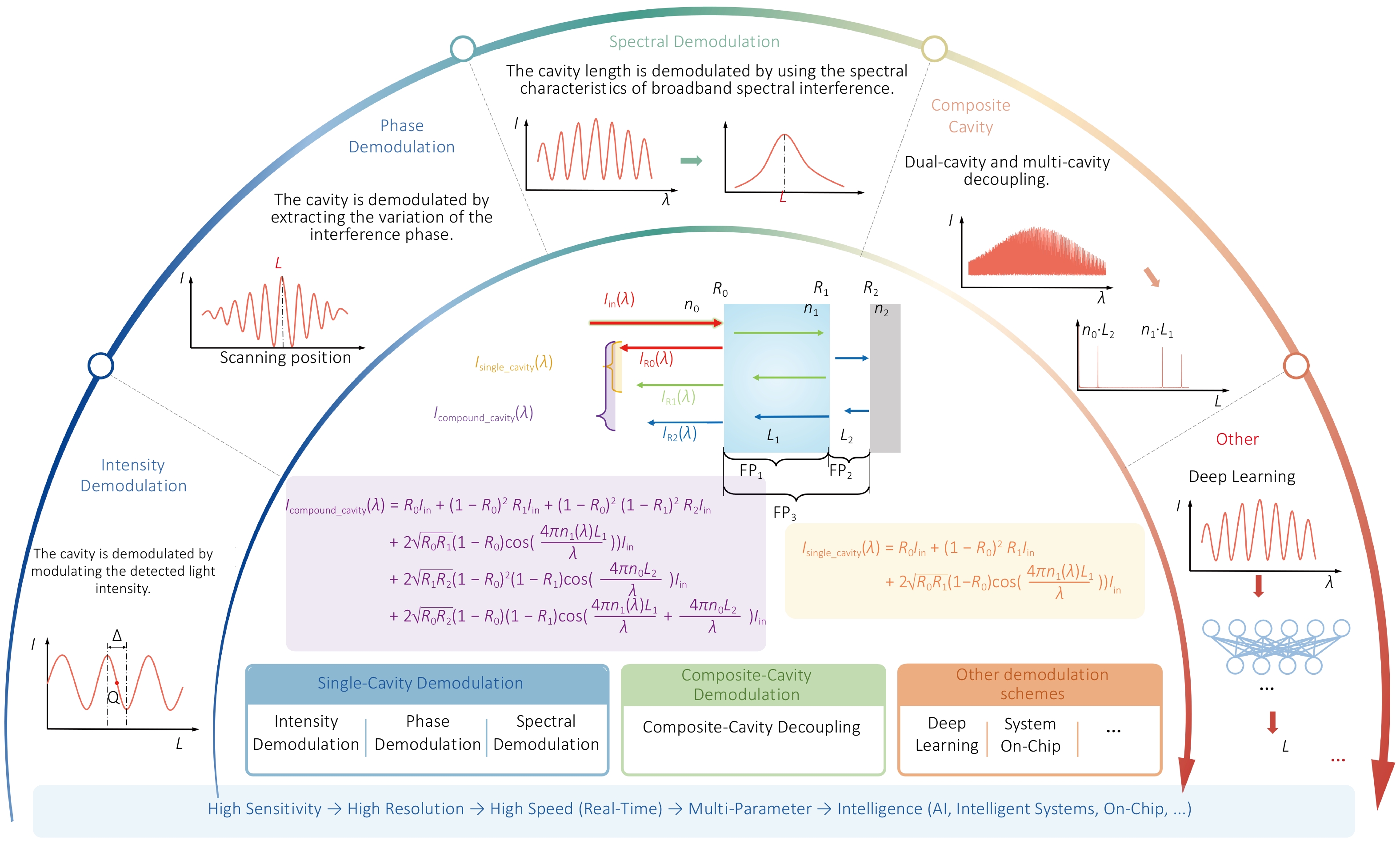
Figure 6. F–P sensor basic demodulation technology roadmap.
\[\begin{split}I_{\mathrm{single}_{\mathrm{cavity}}}= & R_0I_{\mathrm{in}}+(1-R_0)^2R_1I_{\mathrm{in}} \\ & +2\sqrt{R_0R_1}(1-R_0)\mathrm{cos}(\frac{4\pi n_1L_1}{\lambda}))I_{\mathrm{in}}\;.\end{split}\] (20)
Based on the reflected light intensity model, the development of cavity length calculation schemes can be roughly divided into intensity demodulation, phase demodulation, spectral demodulation, and other schemes developed in recent years. Early traditional intensity demodulation schemes used monochromatic light as the light source, utilizing the variation of interference light intensity with optical path difference. Cavity length demodulation could be achieved by detecting the light intensity. The demodulation speed is fast, but the single dynamic range is small, and it is easily affected by the environment64–66. The phase demodulation algorithm for monochromatic light offers higher accuracy, but may suffer from 2π ambiguity and is easily affected by the environment67–68. Around 2000, with the development of broadband light sources, spectrometers, detectors, etc., spectral-based demodulation schemes began to develop, including spectral-domain peak tracking, Fourier transform, spectral comparison, etc.69–70. Among them, white light interferometry offers improved stability, and the spectral comparison approach, in particular, provides extremely high accuracy, making it the current mainstream high-precision calculation scheme. However, spectral comparison is computationally intensive and relatively slow.
Current research on demodulation schemes for F–P-type sensing systems is mainly developing in the direction from high sensitivity to high accuracy, and then to high accuracy, multi-parameter, and intelligent approaches71. Relying on the development of MEMS technology, the fabrication of F–P-type sensors has become more convenient, leading to the emergence of F–P sensors with composite cavity structures for simultaneous measurement of temperature-pressure, temperature-salinity, temperature-refractive index, etc.61,72,73. The composite cavity model is as follows:
\[\begin{split} & I_{\mathrm{compound}_{\mathrm{cavity}}}(\lambda)=R_0I_{\mathrm{in}}+(1-R_0)^2R_1I_{\mathrm{in}}+ \\ & (1-R_0)^2(1-R_1)^2R_2I_{\mathrm{in}} \\ &\left. +2\sqrt{R_0R_1}(1-R_0)\mathrm{cos}\left(\frac{4\pi n_1(\lambda)L_1}{\lambda}\right)\right)I_{\mathrm{in}} \\ & +2\sqrt{R_1R_2}(1-R_0)^2(1-R_1)\mathrm{cos}\left(\frac{4\pi n_0L_2}{\lambda}\right)I_{\mathrm{in}} \\ & +2\sqrt{R_0R_2}(1-R_0)(1-R_1)\mathrm{cos}\left(\frac{4\pi n_1(\lambda)L_1}{\lambda}+\frac{4\pi n_0L_2}{\lambda}\right)I_{\mathrm{in}}\ .\end{split}\] (21)
For the calculation of composite cavities, decoupling of the two-cavity information is one of the most important steps. Through Fourier transform, time-frequency analysis, etc., separate extraction and decoupling of the two cavities can be achieved56. In recent research on demodulation schemes, neural networks have begun to be directly used as demodulation tools. Deep learning-based methods allow a network to directly learn the mapping from spectra to cavity length (or multiple cavity lengths) from a large amount of experimental spectral data74,75.
4.2 Demodulation techniques for single-cavity fiber-optic F–P sensors
4.2.1 Intensity demodulation techniques
Among the demodulation techniques for F–P-type sensors, intensity demodulation offers advantages such as system simplicity, fast response speed, and low cost76. However, issues such as the cosine nonlinearity between interference light intensity and cavity length, the sensitivity of the static operating point to ambient temperature, and fluctuations in optical path loss have long constrained the accuracy and stability of traditional intensity demodulation methods. The core of traditional intensity demodulation is to operate the system at the "quadrature point" (Q-point) of the interference curve, as shown in Fig. 7(a), where the slope is maximum (approximately linear region). When an external signal causes a cavity length change, the reflected light intensity is approximately linearly related to the cavity length (ΔL = αΔI), where α is the detection sensitivity64. To overcome the aforementioned limitations, researchers have developed various improved techniques, including operating point control methods, phase quadrature stabilization methods, multi-wavelength intensity demodulation, and harmonic component amplitude ratio methods.
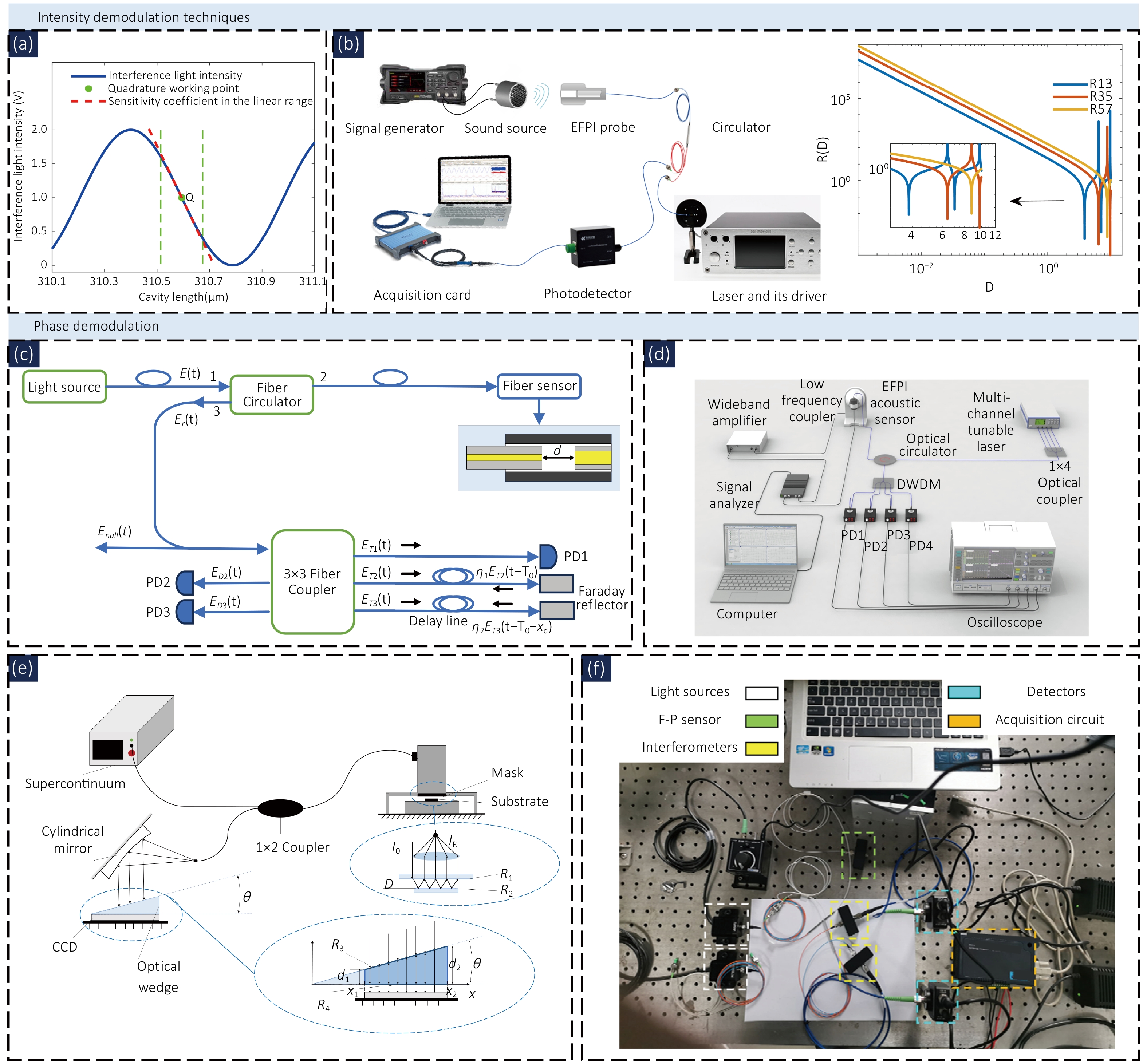
Figure 7. (a) Relationship between the F–P cavity length and the interference light intensity, (b) Harmonic amplitude ratio demodulation system and Curve of Rmn varying with D, (c) phase-shifting optical demodulation system, (d) acoustic signal testing system based on four-wavelength demodulation. (e) Non-scanning optical correlation demodulation system, (f) dual Fizeau demodulation system. Figure reproduced from: (a) ref76, IEEE; (b) ref64, Optica Publishing Group; (c) ref82, IEEE; (d) ref83, Optica Publishing Group; (e) ref89, Optica Publishing Group; (f) ref90, Springer Nature.
To break the strict dependence of the operating point control method on the Q-point and expand the demodulation range, in 2024, Qiu et al. proposed a demodulation algorithm based on the amplitude ratio of harmonic components (ARHC). This method uses Bessel function expansion of the interference signal and obtains the intensity ratio of the fundamental frequency to the double frequency via Fourier transform. This ratio is related only to the amplitude of the signal under test and is independent of the initial phase introduced by the static cavity length. Figure 7(b) shows the acquisition system and the relationship among the amplitude ratio, cavity length, and harmonic components. This method achieves a larger demodulation range, higher accuracy, and better environmental adaptability.
Zuo et al.(2024) proposed a magnetic field sensor based on dual-wavelength elliptical demodulation. An external magnetic field changes the complex refractive index of the magnetic fluid, thereby modulating the reflected light intensities at two wavelengths. The two light intensities satisfy an elliptical function relationship, and the semi-major axis of the ellipse is inversely proportional to the magnetic field strength. This scheme exhibits good linearity in the range of 0–50 Gs, with a measurement accuracy of 2.62 Gs, and the ratio processing effectively suppresses light source fluctuations and optical path disturbances77.
Li et al. (2025) applied feedback-type single-wavelength intensity demodulation technology to real-time gear fault detection, the reflected light is received by a photodetector, and an FPGA analyzes the demodulated signal in real time and controls the filter voltage to dynamically lock the Q-point. The system acquires vibration signals of 27 gear health states at a sampling rate of 100 kHz78.
To overcome the problems of light source fluctuation, fiber disturbance, and Q-point drift caused by temperature in traditional intensity demodulation, Ye et al. (2026) proposed a high-stability quadrature point demodulation technique. Common-mode interference is eliminated by calculating the ratio of the sensing signal to the reference signal, while the low-frequency zero-drift component is extracted to provide feedback control of the filter center wavelength, actively compensating for Q-point drift. The nonlinear error is less than 1.5% in the range of 25 °C to 300 °C79.
For multi-channel scenarios, Wang et al. (2026) designed an intensity demodulation system integrating a biconical MZI sensor and a ceramic ferrule FPI sensor. The FPI sensor utilizes the characteristic that its light intensity varies periodically with temperature to achieve high-precision measurement in critical intervals such as 44 °C to 46 °C (detection limit 0.02 °C)80.
Intensity demodulation offers a simple configuration and fast response, making it well suited for rapid dynamic measurements where cavity-length variations remain small and within an approximately linear range. In addition, maintaining the operating point near the quadrature point enables high sensitivity.
4.2.2 Phase demodulation
Unlike intensity demodulation, phase demodulation directly extracts the phase change of the interference light, fundamentally avoiding light intensity fluctuations and nonlinear distortion. According to the carrier generation method, it can be divided into two major categories: active carrier modulation and passive phase shift detection. The phase-generated carrier (PGC) is an active modulation method that shifts the signal spectrum to the high-frequency region by introducing a high-frequency carrier in the reference arm, thereby suppressing low-frequency environmental noise. An improved Arctan demodulation scheme proposed by Zhang et al. (2026). Orthogonal signals independent of θ and C were constructed using the sine and cosine components of the fundamental frequency and double frequency and their differentials, with a measured total harmonic distortion below 0.5%81.
As shown in Fig. 7(c)82, Liu et al.(2021) used a Faraday Michelson interferometer with passive demodulation based on a 3×3 coupler, requiring no external modulation. The 3×3 coupler and two Faraday mirrors formed a demodulator with a fixed phase shift of 120°. Combined with linear fitting and the DCM algorithm, they successfully demodulated a large vibration signal of 3.5 kHz with an amplitude of 12.9 μm. Shi et al. (2022) proposed a single-wavelength passive phase shift demodulation technique. After eliminating the DC and AC amplitude differences using ellipse fitting, the phase was demodulated by arctangent. This scheme achieved linearity R2 = 0.99993 in the amplitude range of 0.01–2250 nm84.
Huang et al.(2024) proposed an improved dual-wavelength method based on prior information. A reference strong ultrasound signal was introduced to pre-construct a complete Lissajous figure, and ellipse fitting was used to obtain parameters of DC, AC, and phase difference. Linearity reached 0.9989 in the sound pressure range of 0.20–13.36 Pa85. Zhang et al. (2024) proposed a quadrature-phase three-wavelength demodulation method. The three interference signals differ sequentially by (2m+1/2)π and (2m+1)π. After eliminating the DC component by linear fitting, the phase was demodulated using arctangent86. Zhang et al.(2022) proposed a four-wavelength quadrature phase demodulation technique suitable for extrinsic F–P interferometer (EFPI) sensors and dynamic signals, as shown in Fig. 7(d). Four wavelengths were selected according to the free spectral range (FSR) of the EFPI. Linear fitting was used to obtain the linear equations of two sets of anti-phase signals, which were normalized to obtain standard orthogonal signals, and then the phase was demodulated by differential cross-multiplication. Experiments showed linearity of 0.9999 in the sound pressure range of 0.24–6.19 Pa at 250 Hz, with a frequency response covering 1 Hz to 100 kHz83.
Phase demodulation is well suited for displacement and vibration measurements that demand high resolution, linearity, and fast dynamic response, while quadrature-phase detection effectively mitigates the influence of optical-intensity fluctuations. However, because monochromatic phase measurements suffer from a 2π ambiguity, determining the absolute cavity length requires either phase unwrapping or the use of additional absolute-reference information.
Monochromatic light phase demodulation utilizes the high coherence of lasers to achieve high-precision measurement via phase extraction. However, narrow-linewidth light sources cannot provide absolute cavity length information. With the development of broadband light sources, the cross-correlation demodulation method for white light interferometry has been developed. The basic principle involves using a reference interferometer. When the reference optical path length exactly matches the sensing optical path length, the position of the zero-order correlation peak is the absolute cavity length, free from periodic ambiguity constraints. Correlation demodulation is primarily classified into scanning and non-scanning types. Scanning correlation demodulation changes the reference optical path length through mechanical or light source tuning in the time dimension to achieve matching87. In contrast, non-scanning correlation demodulation expands different optical path differences spatially at once, with different positions on the detection array corresponding to different reference cavity lengths88.
We (2022) designed a non-scanning hardware optical correlation system based on a Fizeau interferometer for the dynamic detection of mask-wafer gap in surface plasmon lithography, as shown in Fig. 7(e). The light intensity corresponding to each pixel on the CCD is the optical cross-correlation result between the sensing cavity length and the two beams of light corresponding to the wedge thickness. The demodulation system achieved a resolution better than 0.30 nm and a static stability of ±0.12 nm in the range of 3.0–6.0 μm89. We (2023) proposed a dual Fizeau interferometer demodulation system, as shown in Fig. 7(f). Two orthogonal signals can be used to calculate the phase, and then the absolute cavity length is obtained from the periodic relationship between the dual-wavelength phase difference and the cavity length, extending the limited range of single-wavelength demodulation to 4.74 μm, achieving large-range absolute measurement90.
4.2.3 Spectral demodulation
In addition to intensity demodulation and phase demodulation, another major class of methods directly processes the reflection spectrum of the sensor in the wavelength domain. These methods calculate the cavity length by extracting characteristic features in the spectrum, such as extreme wavelength, frequency components, or correlation peaks. Typically, such methods employ broadband light sources or tunable lasers, combined with spectrometers or scanning filters to obtain interference spectra, thereby enabling absolute cavity length measurement that is immune to fluctuations in light intensity. However, the demodulation speed is limited by the spectral acquisition rate. These methods can be roughly divided into spectral peak tracking, Fourier transform, spectral comparison (cross-correlation), etc.91. The most direct spectral demodulation method is to track the spacing between adjacent peaks or dips in the interference spectrum. The cavity length d and the wavelength spacing Δλ between adjacent peaks (or dips) satisfy d = λ2/(2nΔλ). Jiang (2008) used a tunable F–P filter (FFP-TF) to scan the spectrum and calibrated the wavelength with an acetylene gas cell, improving the measurement resolution from 25 μm to 1 μm92. Chen et al. (2020) proposed a square peak-to-peak algorithm. The reflection spectrum was transformed to the frequency domain, the DC component was filtered out, and then squared. For sensors with a cavity length of 15–25 μm, the measured maximum error was only 0.030 μm91. Mei et al. (2015) proposed a multi-extremum tracking technique. A tunable laser was used to scan 1525–1565 nm with high precision to obtain the exact wavelengths of all 33 peaks and 32 dips. The interference order was obtained by linear fitting of all extrema, achieving a resolution of 1 nm and a dynamic range covering 250–3000 μm93.
The Fourier transform method converts the wavelength-domain interference spectrum into the frequency domain via FFT, where the position of the main peak corresponds to the cavity length. This method offers fast processing speed, but the resolution is limited by the spectral sampling range and number of points. As shown in Fig. 8(a), Hai et al. (2024) proposed an improved algorithm combining FFT with mean square error (MSE) for a sapphire sandwich-structure F-P pressure sensor, combining the Fourier transform method and spectral comparison. The fitting error under a pressure of 0–10 MPa was less than 0.025%94. The spectral comparison method performs a correlation operation between the measured spectrum and a series of ideal spectra with known cavity lengths. The cavity length corresponding to the correlation peak is the measured value. This method inherently offers noise immunity and sub-pixel accuracy. Shao et al. (2021) used cross-correlation to demodulate a sapphire composite cavity, obtaining a pressure sensitivity of 355.8 nm/MPa and a temperature sensitivity of 1.64 nm/°C, as shown in Fig. 8(b)95. Li et al. (2024) used a 48-channel arrayed waveguide grating (AWG) as a spectroscopic element to perform FFT, frequency estimation, and phase calculation in real time, achieving a demodulation rate of 200 kHz, a cavity length range of 60–700 μm, and a resolution better than 0.22 nm96.
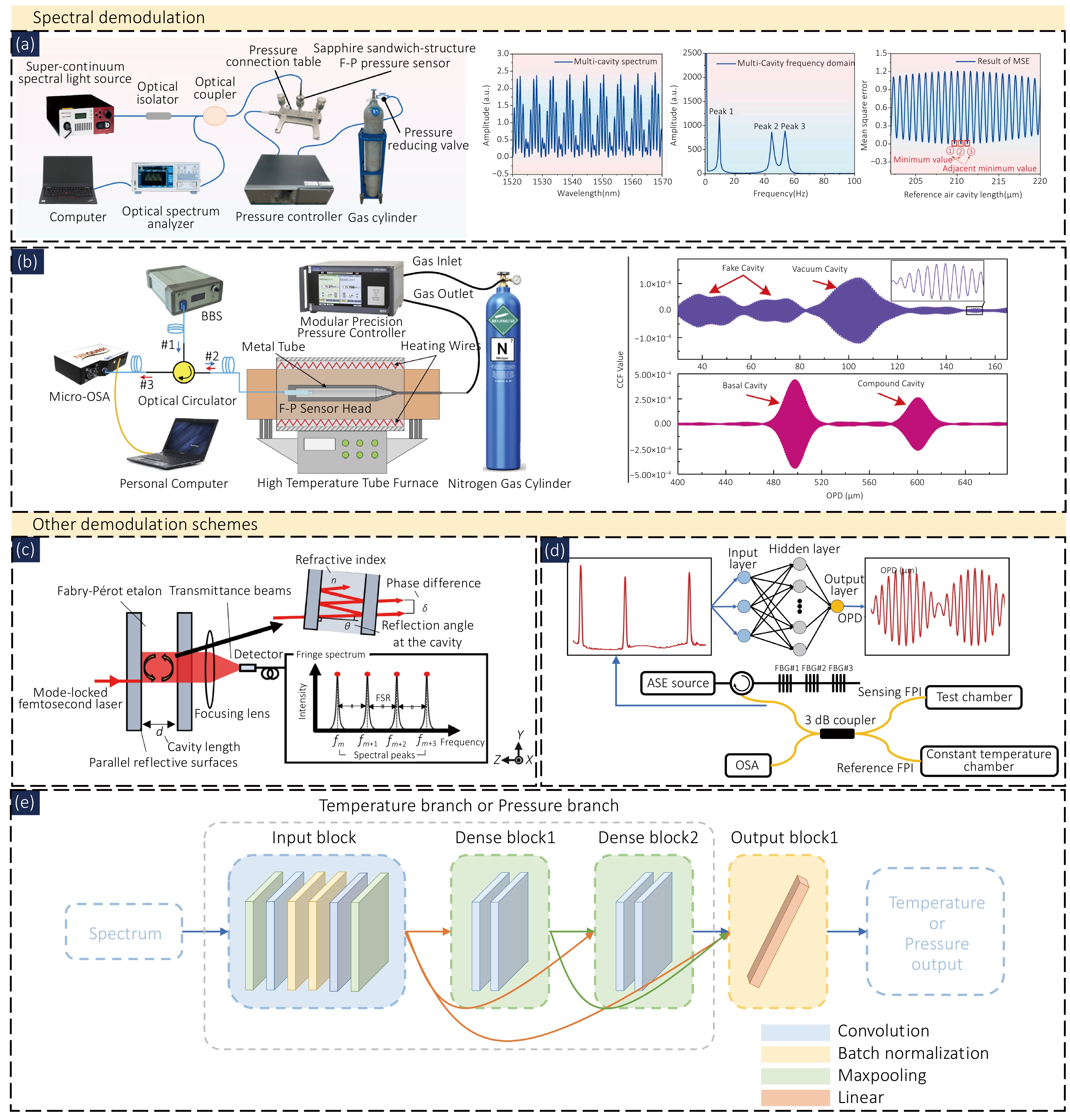
Figure 8. (a) Testing system of sapphire sandwich-structured F–P pressure sensor, (b) high-temperature pressure sensing system and cross-correlation function of two ranges; (c) Beam propagations at a Fabry–Perot etalon and its fringe spectrum, (d) Intensity Demodulation of Optical Vernier Effect; (e) Single-parameter pre-training branch model. Figure reproduced from: (a) ref94, MDPI; (b) ref95, Optica Publishing Group; (c) ref97, Optica Publishing Group; (d) ref98, IEEE Xplore; (e) ref100, Elsevier Ltd.
Spectral demodulation extracts the absolute cavity length from characteristic wavelengths, spatial-frequency components, or the full profile of a broadband interference spectrum. Its performance is governed primarily by the spectral bandwidth, resolution, sampling interval, and fringe visibility. Among the commonly used techniques, peak/valley tracking works well for static or slowly varying spectra that exhibit well-defined extrema and high visibility; Fourier-transform-based methods are effective for broadband, approximately periodic spectra and can resolve composite cavities when their frequency-domain peaks are distinguishable; and spectral comparison/cross-correlation approaches leverage the entire spectral shape, offering higher accuracy for absolute cavity-length measurements at the expense of increased computational cost.
4.2.4 Other demodulation schemes
In recent years, several improved techniques incorporating new principles or new tools have emerged. They either improve accuracy based on traditional methods or leverage optoelectronic devices and intelligent algorithms to expand system capabilities, providing more options for engineering applications of fiber-optic F–P sensors. Matsukuma et al. (2023) proposed an improved scheme spanning multiple free spectral ranges, as shown in Fig. 8(c). Two peaks separated by an integer k FSRs were selected. Using an air-gap F-P etalon with FSR ≈ 200 GHz and N = 62, after optimizing with k = 31, the standard deviation of repeated measurements was only 3.8 nm97. Zhang et al. (2024) combined the optical Vernier effect with a three-layer backpropagation neural network, as shown in Fig. 8(d). Using only the relative light intensity ratios at three wavelengths, the interferometer's optical path difference was output after training, with a relative error ≤ ±1.23%98. Chen et al. (2025) used an arrayed waveguide grating (AWG) and a convolutional bidirectional gated recurrent unit (CNN BiGRU) network, converting wavelength shifts into 28-channel transmitted light intensities. The network directly predicted three characteristic wavelengths from the multi-channel light intensity values74. Li et al. (2026) arranged six micro-sphere FPI pressure sensors on the seat surface and backrest key pressure areas, using a MEMS optical switch for time-division multiplexing99.
In addition to state recognition, deep learning can also automatically extract parameter features directly from raw spectra, making it particularly suitable for multi-parameter measurement where cross-sensitivity exists. As shown in Fig. 8(e), Li et al. (2026) constructed a dual-branch DenseNet network for a cascaded EFPI-FBG sensor. The final mean absolute error for temperature was 0.907 °C, and for pressure it was 0.035 MPa, with a single-spectrum demodulation time of 0.38 ms100.
To achieve multi-parameter measurement or in-situ temperature compensation for F–P sensors, composite cavity sensors have been developed, integrating multiple parameters such as temperature and pressure into a single sensing head. Wang et al. (2021) directly bonded a silicon-based pressure-sensitive diaphragm to a silicon substrate to form a dual-cavity temperature-pressure sensor. The demodulation system and spectral schematic are shown in Fig. 9(a). A bandpass filter was used to separate the independent spectrum of each sub-cavity, and then the peak tracking method was used to accurately extract the cavity length. The pressure-temperature cross-sensitivity of this sensor was as low as 5.96 Pa/°C61.
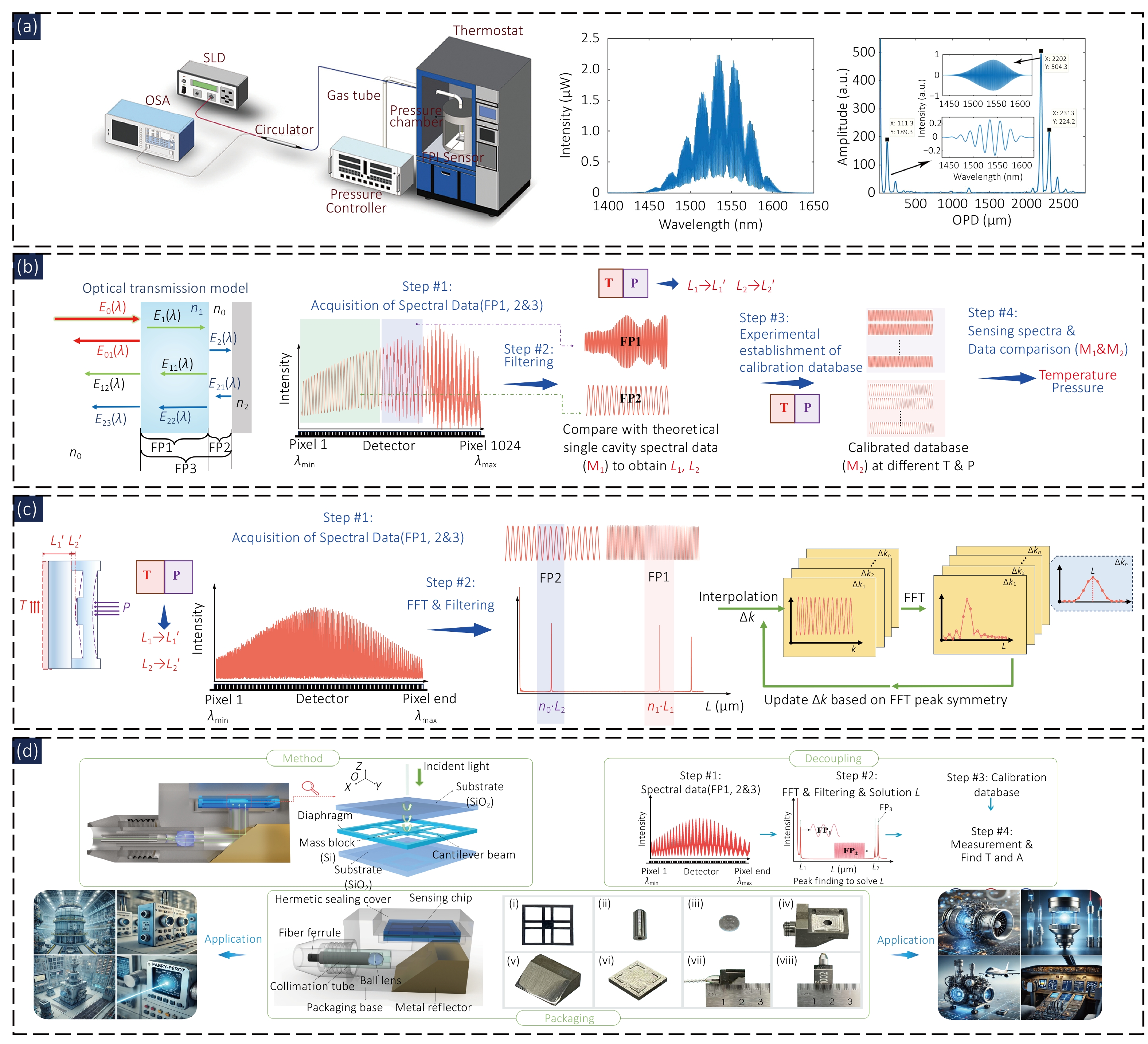
Figure 9. Composite F–P cavity sensors. (a) All-silicon temperature–pressure composite cavity and Fourier transform demodulation, (b) sapphire–metal sheet temperature–pressure composite cavity and time–frequency analysis decoupling, (c) all-sapphire temperature–pressure composite cavity and peak-shift-corrected Fourier transform, (d) silica temperature–acceleration composite cavity and Fourier transform demodulation. Figure reproduced from: (a) ref61, Optica Publishing Group; (b) ref56, IEEE; (c) ref57, Springer Nature; (d) ref58, Springer Nature.
In 2025, our research group also designed a sapphire-metal composite cavity sensor for composite-cavity temperature-pressure sensing. The sensor consists of a sapphire substrate and a metal diaphragm56. As shown in Fig. 9(b), by controlling the resolution of the spectrometer, the information from the two cavities was segmented along the wavelength on the spectrometer. After confirming the segmentation positions through time-frequency analysis, the interference signals of the two sub-cavities were decoupled. In the ranges of 0–500 °C and 0–4 MPa, the temperature accuracy was 0.35% FS, and the pressure accuracy was 0.52% FS. To further improve high-temperature performance, in 2026 we developed an all-sapphire composite cavity sensor and proposed an adaptive peak-shape-corrected FFT algorithm (APSC-FFT)57. As shown in Fig. 9(c), by iteratively adjusting the resampling interval in the wavenumber domain to make the FFT peak symmetric, the demodulation accuracy of the Fourier transform decoupling algorithm was further improved. In the ranges of 28–800 °C and 0–1.2 MPa, the temperature system error was 0.13% FS, and the pressure error was 0.18% FS. In the same year, we extended this composite cavity design concept to acceleration measurement, as shown in Fig. 9(d), adopting a three-layer chip structure: a glass substrate forms the temperature cavity, and an air cavity is formed between the glass and the proof mass58. For demodulation, FFT combined with bandpass filtering was employed to separate the spectra, the peak tracking method was used to extract the cavity length, and real-time temperature compensation was performed through calibration curves. In a 60-hour stability test at 350 °C and 17.5 MPa, the cavity length drift was less than 0.1 nm, and the cross-axis sensitivity was 0.281%.
Machine learning offers a direct approach to establishing nonlinear mappings between F–P spectra and cavity length or other target physical quantities. However, its practical deployment demands careful consideration of training-data representativeness, model generalization, and real-time performance. To minimize the model's dependence on specific experimental conditions, the training data should encompass a wide range of measurement ranges, signal-to-noise ratios, and operating environments (e.g., temperature and pressure). Moreover, sensor-to-sensor fabrication variations and long-term drift in the interrogation system can cause distribution shifts between training and actual measurement data, underscoring the need to further enhance model robustness across different sensors and operating conditions130,131. For dynamic and embedded demodulation applications, it is also essential to balance demodulation accuracy with real-time performance by carefully evaluating model size, computational latency, and hardware resource consumption.
4.3 Analysis of demodulation techniques in special environments
The application of fiber-optic F–P sensors in extreme environments characterized by high temperature, high pressure, strong electromagnetic interference, and confined spaces imposes stringent requirements on the stability, accuracy, dynamic range, and real-time performance of demodulation methods. Different demodulation techniques differ in their principles, system complexity, environmental adaptability, and performance metrics, and thus must be selected according to specific operating conditions. Intensity demodulation directly reflects cavity length changes by detecting variations in interference light intensity. It features the simplest system structure and the fastest response speed, but is susceptible to light source fluctuations and environmental disturbances. Phase demodulation extracts the phase change of the interference signal, offering good linearity and a large dynamic range, but with relatively higher system complexity. Spectral-domain demodulation directly uses the reflection spectral characteristics of a broadband light source or tunable laser to calculate the absolute cavity length, without being affected by light intensity fluctuations, but the demodulation speed is limited by the spectral acquisition equipment. With the development of deep learning, on-chip devices, and related technologies, fiber-optic F–P sensing demodulation schemes, when integrated with traditional demodulation methods, can accommodate increasingly complex application requirements, including integration, multi-parameterization (composite cavities), and in-situ compensation.
5 Applications in extreme scenarios
With the continued advancement of aerospace engineering, deep-earth energy exploration, the nuclear industry, and marine engineering, extreme environments, characterized by high temperature, high pressure, corrosive media, strong electromagnetic fields, and radiation, are imposing ever more stringent demands on sensor stability and reliability. Owing to their compact footprint, corrosion resistance, and inherent immunity to electromagnetic interference, fiber-optic sensors have emerged as a key technological solution for monitoring under such complex operating conditions.
The suitability of F–P sensors for various extreme environments depends not only on the target measurand, but also on the cavity architecture, fabrication method, and underlying sensing mechanism. Representative architectures include: (i) intrinsic in-fiber microcavities, typically fabricated by fusion splicing or femtosecond laser micromachining, which transduce external perturbations into changes in cavity length or refractive index; (ii) extrinsic cavities incorporating diaphragms or proof masses, where mechanical deformation under pressure or acceleration alters the air-gap length, offering high sensitivity, though thermal mismatch and fatigue remain concerns; (iii) MEMS-integrated cavities formed by silicon etching and wafer-level bonding, which benefit from batch fabrication and precise dimensional control, yet are constrained by the limited tolerance of silicon-based materials to ultra-high temperatures and aggressive corrosion; (iv) dual- or composite-cavity structures, which combine multiple cavities with distinct sensitivity and thermal coefficients, enabling simultaneous multiparameter measurement and effective cross-sensitivity decoupling; and (v) 3D-microprinted cavities fabricated via two-photon polymerization, which allow flexible three-dimensional geometries for customized sensing, but face challenges in material shrinkage, thermal stability, and reproducibility. These configurations operate through distinct transduction principles, whether changes in cavity length or refractive index, deformation of mechanical sensing elements, or differential responses among multiple cavities. Furthermore, the selection of materials, fabrication processes, and packaging schemes must be tailored to specific service conditions, including high temperature, high pressure, corrosion, strong electromagnetic fields, and radiation. The following sections therefore discuss the structural design and environmental adaptability of F–P sensors in representative extreme-environment applications.
5.1 Applications in high-temperature environments
Liu et al. (2026) proposed an all-silica fiber-optic F–P vibration sensor based on MEMS and laser welding. A beam-proof mass sensitive structure was fabricated using femtosecond laser. Combined with a gold-plated FBG and three-wavelength demodulation, temperature decoupling was achieved. The sensitivity at 800 °C was 0.0082 rad/g, and the accuracy after compensation was better than 2.31% F.S.101.
Li et al. (2026) developed a microsphere-lens-enhanced fiber-optic F–P high-temperature strain sensor using a cascaded structure of EFPI and GFBG. A microsphere lens was used to focus the optical field to maintain fringe contrast. The sensitivity at 800 °C was 22.87 nm/με, with an error < 2.17% F.S., and the sensor could withstand >4000 με (Fig. 10(a)-i)102.
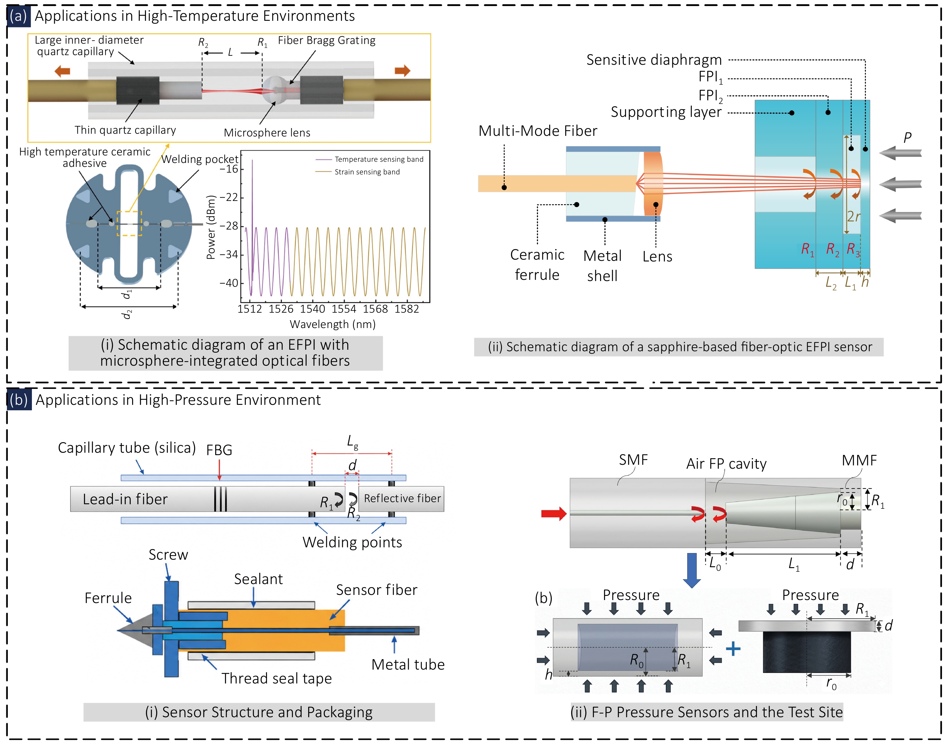
Figure 10. High-temperature and high-pressure fiber-optic F–P sensing applications. (a) High-temperature environment application, (b) high-pressure environment application; (a) i Schematic diagram of an EFPI with microsphere -integrated optical fibers, (a) ii Schematic diagram of a sapphire-based fiber-optic EFPI sensor, (b) i All-silica high-temperature resistant fiber-optic F–P air pressure sensor, (b) ii hard-core diaphragm-enhanced all-fiber F–P high-pressure sensor. Figure reproduced from: (a) i ref102, Optica Publishing Group; (a)ii ref39, Optica Publishing Group; (b) i ref103, Wiley-VCH Verlag; (b) ii ref105, IEEE.
Liao et al. (2025) developed a sapphire MEMS dual-cavity F-P pressure sensor. Three layers of sapphire were bonded to form a vacuum pressure cavity and a temperature measurement cavity. The dual cavities independently decoupled pressure and temperature. The resolution was 0.1% F.S. in the range of 0–1 MPa, and the pressure accuracy at 1500 °C was 0.86% F.S. (Fig. 10(a)-ii)39.
5.2 Applications in high-pressure environments
Zhu et al. (2025) developed an all-silica high-temperature resistant fiber-optic F–P air pressure sensor. A quartz capillary and an optical fiber were CO2 laser welded to form a sealed cavity. A cascaded femtosecond FBG was used to achieve in-situ temperature compensation. The sensitivity in the range of 0–14 MPa was 58 nm/MPa, with a room temperature error of 0.8% F.S. In the range of 25–655 °C, the sensor could measure 0–3.2 MPa, with a zero drift of 0.096% F.S. (Fig. 10(b)-i)103.
He et al. (2023) proposed a quasi-distributed F–P high-pressure sensing scheme based on hollow-core photonic bandgap fibers. Combined with an optically carried microwave interferometry system, multi-node parallel demodulation was achieved. The measurement range was 0–100 MPa, with a pressure sensitivity of –25.6 pm/MPa, a temperature cross-sensitivity of only –0.02 MPa/°C, and a spatial resolution of centimeter level104.
He et al. (2022) developed a hard-core diaphragm-enhanced all-fiber F–P high-pressure sensor. A high-germanium-doped multimode fiber and a single-mode fiber were spliced to form a cavity. The hard-core diaphragm multiplied the sensitivity, with a mechanical resonance frequency >100 kHz. The sensitivity in the range of 40–200 °C was 0.23 V/MPa, with hysteresis <1.5% and repeatability <0.8%. The results were consistent with those of a Kistler sensor (Fig. 10(b)-ii)105.
Dai et al. (2022) proposed a suspended fiber-optic F–P high-pressure sensor. By adjusting the length ratio of the capillary to the air cavity (L2/L1), controllable sensitivity enhancement was achieved. When L2/L1 increased from 13.4 to 114.6, the sensitivity increased from –361.41 to –2975.21 pm/MPa. The measurement uncertainty in the range of 0–80 MPa was 0.03%, and the temperature crosstalk was 0.0011 MPa/°C106.
5.3 Applications in liquid environments
Marine monitoring: Zhao et al. (2025) studied a silicon-based F–P interferometric temperature sensor. A single-crystal silicon chip was used as the sensitive chip, utilizing the high thermo-optic coefficient of silicon to achieve high-sensitivity temperature measurement without the need for coating. A current-modulated DFB laser combined with an HCN gas cell for wavelength calibration and a cross-correlation algorithm was used to improve stability107. The TC4 titanium alloy pressure-resistant packaging withstands pressure up to 115 MPa, making it suitable for full-ocean-depth applications. Key specifications: sensitivity 75 pm/°C, resolution 6.2×10⁻⁵ °C, measurement range 0–35 °C. In the South China Sea trial, the standard deviation of the difference from the SBE37 CTD was <0.025 °C for the 0–3895 m profile, and the observation deviation at the 3900 m seabed over 87 days was only 0.0031 °C with no significant drift, demonstrating suitability for deep-sea profile observation, long-term seabed monitoring, and climate research (Fig. 11(a)-i).
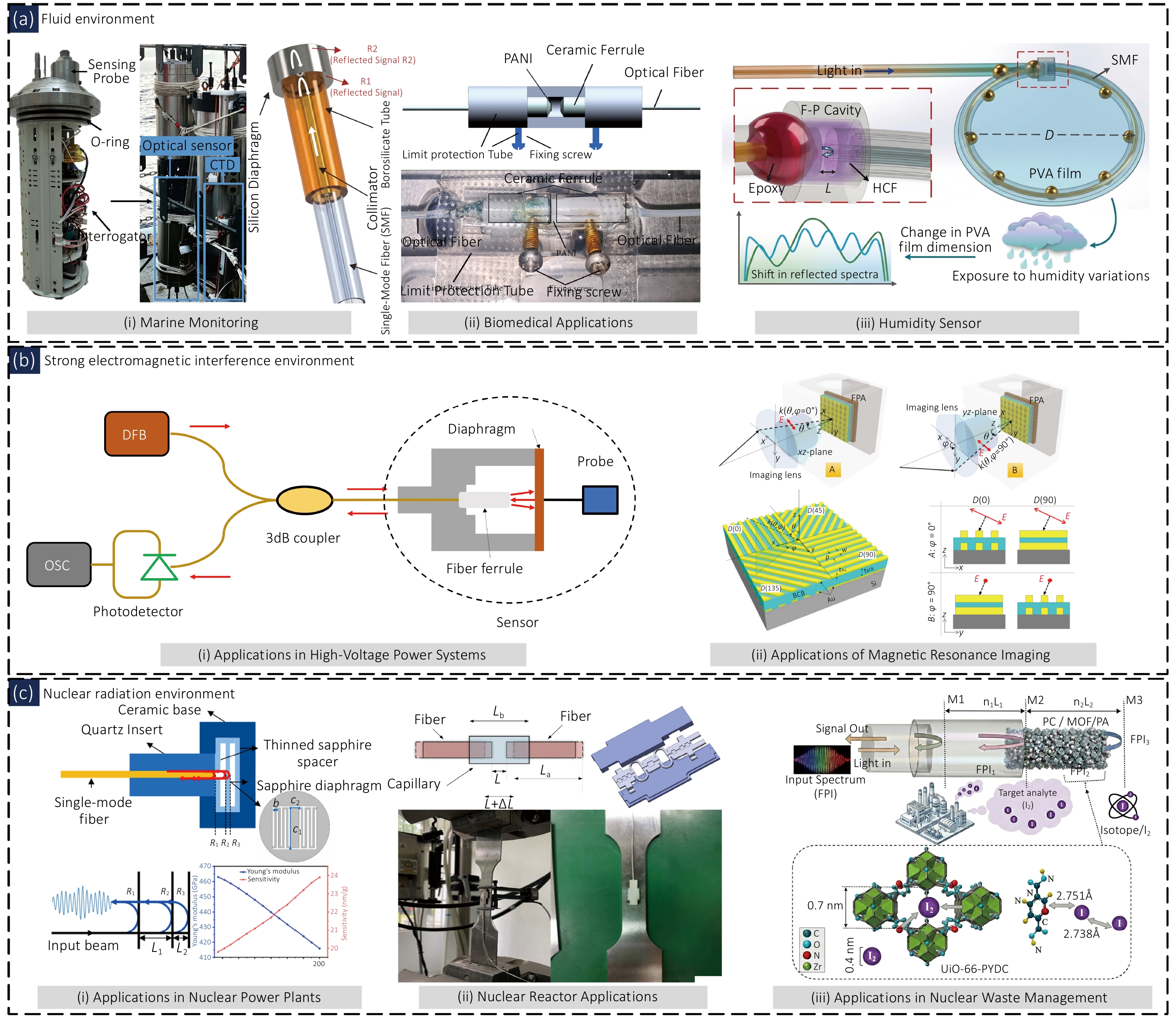
Figure 11. Typical fiber-optic F–P sensing applications in extreme environments. (a) Liquid environment application, (b) strong electromagnetic interference environment application, (c) nuclear radiation environment application; (a)i ocean monitoring, (a)ii biomedical application, (a)iii humidity sensor, (b)i high-voltage power system application, (b)ii nuclear magnetic resonance imaging (MRI) application, (c)i nuclear power plant application, (c)ii nuclear reactor application, (c)iii nuclear waste monitoring application. Figure reproduced from: (a)i ref107, IEEE; (a)ii ref108, Elsevier; (a)iii ref109, IEEE; (b)i ref110, IOP Science; (b)ii ref112, MDPI; (c)i ref113, MDPI; (c)ii ref54, MDPI; (c)iii ref114, Academic Press Inc.
Biomedicine: Wang et al. (2025) proposed a fiber-optic F–P cavity pH sensor based on a polyaniline deposited film. A polished fiber end face served as the cavity mirror, and a PANI sensitive film was deposited by in-situ oxidative polymerization. Reversible protonation/deprotonation changes the refractive index of the cavity to achieve pH response, with an in-fiber grating for temperature compensation108. The sensor dimensions are 40 mm × 12 mm, with a measurement range of pH 2–12. The linearity at 0 °C is R2 = 0.98838, the equivalent cavity length sensitivity is −1.228 μm/pH, and the wavelength sensitivity is −0.28682 nm/pH. It exhibits good linear response at low temperature and is suitable for medical fluid detection, biological fermentation, and in-situ monitoring of chemical processes (Fig. 11(a)-ii).
Humidity detection: Yang et al. (2026) developed an ultra-sensitive fiber-optic F-P humidity sensor based on a PVA thin film and a note-shaped open cavity structure. The interference cavity directly interacts with the external environment through a cold splice109. In the range of 6.12%–16.69% RH, the wavelength sensitivity reaches 60.25 nm/%RH, effectively suppressing temperature interference. This provides a high-performance, electromagnetic interference immune sensing solution for online monitoring of trace moisture in high-voltage power equipment such as GIS (Fig. 11(a)-iii).
5.4 Applications in strong electromagnetic interference environments
High-voltage power systems: Zhang et al.(2022) studied a fiber-optic sensing system based on F–P interference. A charge induction probe and a piezoelectric thin film were used to drive the F–P cavity length change, achieving nanosecond-level partial discharge signal detection110. The signal-to-noise ratio is 18.73–19.29 dB, and the average sensitivity is 17.2% higher than that of the UHF antenna method. The system is suitable for online partial discharge monitoring and early fault warning of transformers, GIS, switchgears, and other equipment (Fig. 11(b)-i).
Radar stations: Hossain et al. (2023) used an FPI to observe thermospheric OI 630.0 nm nightglow emission and retrieved neutral temperature and wind fields at altitudes of 220–280 km111. For the first time, seasonal variations of thermospheric temperature and wind fields during solar minimum in the Indian equatorial region were obtained. The temperature ranged from 601 to 849 K. The meridional wind agreed with the HWM14 model, and the zonal wind revealed the PRE effect and regional differences, providing ground-based observational support for ionospheric coupling studies and atmospheric model validation.
Nuclear magnetic resonance equipment: Hwang et al. (2020) proposed a dual-layer metallic grating polarizing unit based on an F-P resonance. A dielectric layer between two layers of gold nano gratings forms an F–P cavity, enhancing TM polarization transmission and suppressing TE polarization112. At a wavelength of 4.5 μm, the transmittance is 0.49, and the polarization extinction ratio is 132. The extinction ratio variation is less than 6% over an incident angle range of 0°–25°. The device is suitable for DOFP polarization imaging systems (Fig. 11(b)-ii).
5.5 Applications in nuclear radiation environments
Nuclear power plants: Pang et al. (2026) proposed a sapphire MEMS fiber-optic F–P vibration sensor with all-ceramic packaging using alumina ceramic. A sapphire composite F–P cavity was fabricated by UV laser micromachining113. The sensor operates stably from −55 to 1200 °C, with a room temperature sensitivity of 20.12 nm/g and a sensitivity of 24.89 nm/g at 1200 °C. The resonant frequency is ~3300 Hz, and the bandwidth is 100–1000 Hz. This breaks through the bottleneck of long-term operation of silicon/quartz-based sensors at 800 °C, making it suitable for high-temperature vibration monitoring of the primary circuit and nuclear main pump in nuclear power plants (Fig. 11(c)-i).
Nuclear reactors: We proposed a fiber-optic F-P strain sensing system based on non-scanning correlation demodulation. A double-spring-leaf ring structure transfers the strain of the fuel plate to the F–P cavity54. The sensitivity at 300 °C is 12.6 nm/με, with a dynamic response of 10–500 Hz. The consistency deviation of thermal-hydraulic experimental data is less than 1.5%. Temperature cross-interference is eliminated by cavity length calibration. The system is used for structural health monitoring of pressurized water reactor fuel assemblies (Fig. 11(c)-ii).
Nuclear waste treatment: Gao et al. (2025) proposed a dual-FPI Vernier-effect MOF-functionalized fiber-optic sensor using a UiO-66-PYDC metal-organic framework for specific adsorption of iodine vapor114. The Vernier cascade sensitivity is 77.76 pm/ppb, and the detection limit is 10 ppb. Complementary cancellation of the polymer TOC and TEC suppresses the temperature cross-sensitivity to −3.35 pm/°C. The sensor enables trace iodine monitoring from 0 to 80 °C and is suitable for safety monitoring of radioactive iodine off-gas in the nuclear industry (Fig. 11(c)-iii).
5.6 Applications in other extreme environments
Fiber-optic F–P sensors exhibit broad application potential across interdisciplinary fields. Zhang et al.(2022) fabricated an all-fiber diaphragm-type EFPI using femtosecond laser, achieving linear measurement of 0–7 MPa at an ultra-low temperature of −196 °C, with pressure sensitivities of 111.17 nm/MPa (increasing pressure) and 111.22 nm/MPa (decreasing pressure)115. Li et al. (2024) proposed a dynamic spectral demodulation method based on EFPI, detecting vibration signals as low as 6 Hz by Fourier sideband characteristics, with a sideband sensitivity of approximately 17 mW/g, suitable for earthquake and building health monitoring116. Amoudry et al. (2020) employed a movable D-shaped dielectric mirror in a high-power optical resonant cavity to suppress thermoelastic higher-order transverse mode degeneracy, achieving stable operation at an average intracavity power of 200 kW with a fundamental mode loss of only about 8 ppm117. Xie et al. (2022) designed a VO2/BaF2 stacked F–P multilayer film, utilizing multiple resonances to achieve a mid-infrared normal emissivity close to 0.95 for spacecraft thermal control coatings, with a tunability of 0.78118. Allam et al. (2025) combined a porous silicon F-P interferometer with a molecularly imprinted polymer to achieve selective detection of ticagrelor, with a linear range of 1.0×10⁻⁷–5.0×10⁻⁵ M and a detection limit of 79 nM, which has been applied to pharmaceutical formulations and human plasma analysis119.
6 Future development
Fiber-optic F–P sensing systems are transitioning from a laboratory paradigm of "discrete devices + benchtop equipment + manual algorithms" toward an engineering paradigm characterized by integration, intelligence, and networking. At the physical sensing layer, optical fibers and probes are evolving toward micro/nano fabrication, new material integration, and multi-parameter integration. Spectral readout technology is developing toward chip-scale, high-speed swept-frequency, and spectrometer-free demodulation. At the demodulation level, intelligent algorithms such as deep learning and compressed sensing enhance noise immunity and speed. At the system level, hybrid multiplexing, weak-reflector grating arrays, and on-chip optical switching support large-capacity, low-crosstalk quasi-distributed networking. Ultimately, these technologies rely on low-cost packaging, standardized interfaces, and optoelectronic integrated chips to achieve large-scale deployment in scenarios such as power, medical, and structural monitoring, promoting fiber-optic F–P sensing from the laboratory to industrial sites and daily life. These directions are mutually reinforcing and collectively constitute the frontier research landscape of this field.
(1) Specialty optical fibers and integrated probes
Despite their superior high-temperature and corrosion resistance, sapphire fibers still face practical limitations in terms of multimode transmission, high-temperature cladding, fiber coupling and packaging, and fabrication consistency. The relatively large core diameter and weak optical confinement of conventional sapphire fibers tend to excite higher-order modes, which cause spectral distortion and degrade demodulation stability. Furthermore, the thermomechanical mismatch between sapphire and silica fibers poses additional challenges for high-temperature coupling and packaging. To advance the engineering application of sapphire-fiber sensors, it is therefore critical to improve mode control, thermal compatibility, fabrication consistency, and long-term reliability.
Using single-crystal sapphire fiber as the core matrix, three major trends are emerging: First, evolving from unclad sapphire to high-temperature cladding systems that are stable above 1200 °C, such as spinel, nanoporous alumina, and ion-implanted modified layers, to solve multimode interference and interface failure. An example is single-crystal sapphire fiber fabricated by the LHPG method (Fig. 12(a)-i). Second, developing new fiber materials such as YAG, zirconia-based, and high-melting-point ceramics to extend applicability to ultra-high temperatures of 1400–1800 °C and strong acid/alkali environments, e.g., YAG-clad single-crystal fiber prepared by sol-gel coating. Third, balancing high-temperature resistance, low loss, and single-mode transmission through microstructured design, such as windmill-shaped microstructured sapphire fiber and negative-curvature hollow-core anti-resonant fiber. The latter uses an air core to greatly reduce light-material contact, offering strong corrosion resistance and high-temperature tolerance (Fig. 12(a)-ii)120,121.
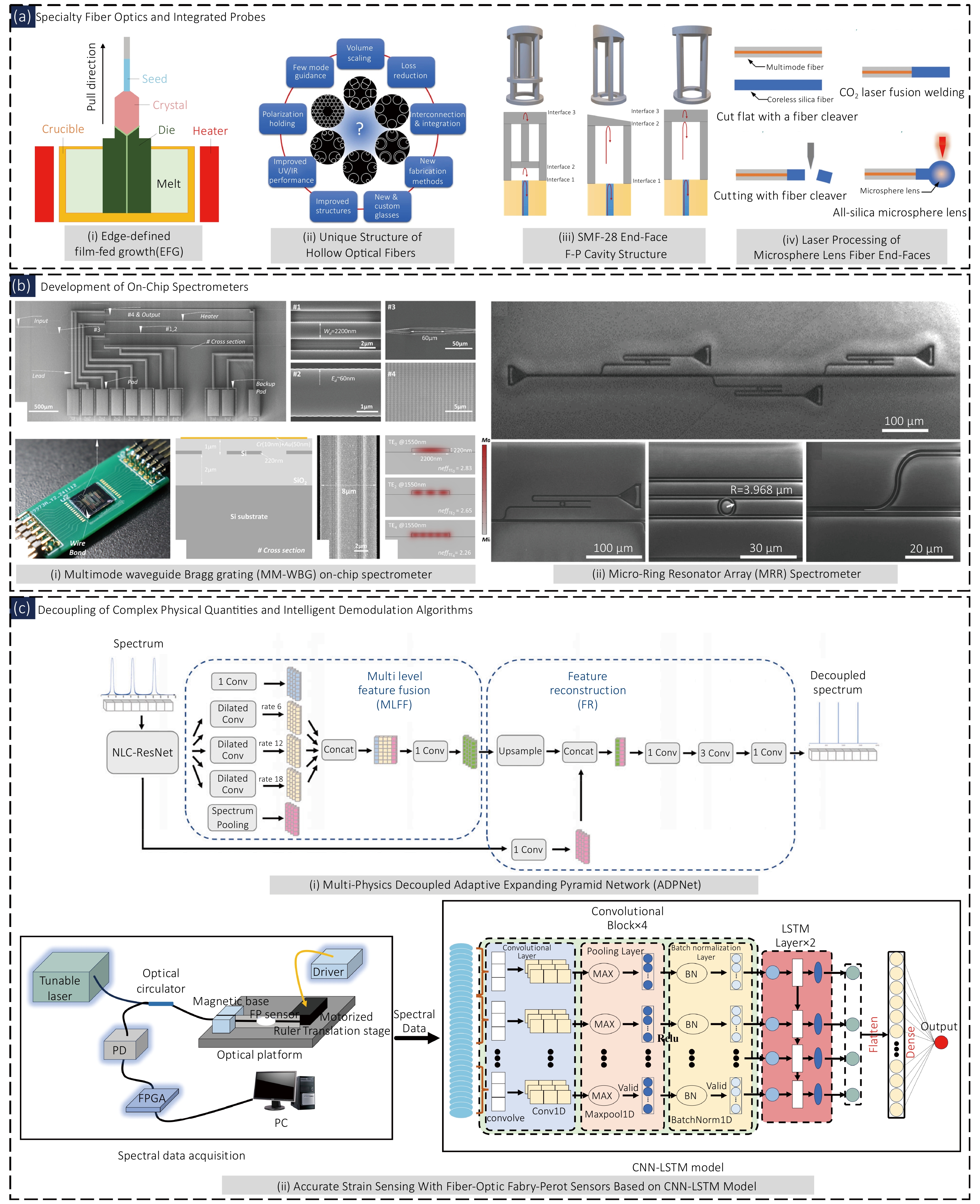
Figure 12. Future development of fiber-optic F–P sensing measurement systems. (a) Development of physical component structures, (b) miniaturization development of spectral reconstruction technology, (c) development of intelligent algorithms; (a)i EFG high-temperature resistant optical fiber, (a)ii special hollow-core fiber structure, (a)iii SMF-28 fiber end-face F-P structure, (a)iv laser-processed fiber end-face, (b)i MM-WBG on-chip spectrometer, (b)ii MRR on-chip spectrometer, (c)i ADPNet decoupling algorithm, (c)ii CNN+LSTM demodulation algorithm. Figure reproduced from: (a)i ref120, AIP Publishing; (a)ii ref121, IOP Science; (a)iii ref123, MDPI; (a)iv ref122, Elsevier; (b)i ref125, Optica Publishing Group; (b)ii ref126, Wiley Online Library; (c)i ref127, IEEE Xplore; (c)ii ref132, IEEE;
Fiber-optic F–P sensing probes are moving from discrete assembly to integrated fabrication on the fiber end face. Sensitive microcavities, elastic diaphragms, and supporting structures are formed in situ at the fiber tip, achieving adhesive-free, packaging-free, solder-joint-free all-optical passive integration, eliminating interfacial thermal stress and high-temperature drift. Probes achieve homogeneous integration using high-temperature resistant materials such as sapphire, MgO, SiC, and high-purity silica, with operating temperatures exceeding 1200 °C (Fig. 12(a)-iii). In fabrication, end-face 3D printing by two-photon polymerization femtosecond laser direct writing can directly shape complex structures such as F–P microcavities and cantilevers, followed by high-temperature degreasing and sintering to achieve ceramization, replacing traditional multi-step MEMS processes and improving consistency and batch production capability (Fig. 12(a)-iv). However, the scalability and reproducibility of F-P sensors remain sensitive to fabrication tolerances. In MEMS fabrication, variations in diaphragm thickness, etching depth, and bonding gap can alter the initial cavity length and mechanical sensitivity. Laser micromachining may introduce cavity-dimensional variations due to fluctuations in laser energy and positioning accuracy, while its point-by-point processing nature limits fabrication throughput. For 3D-microprinted cavities, material shrinkage can further compromise geometric reproducibility. Therefore, stable process control and standardized batch fabrication remain critical for large-scale manufacturing. Multi-FP composite cavity probes can achieve simultaneous measurement of temperature-pressure-strain. For example, an all-ceramic MgO dual-FP cavity probe combined with frequency-domain separation and cross-correlation demodulation achieves crosstalk-free decoupling, meeting the requirements of multi-physics coupling monitoring122–124.
(2) Miniaturization development of spectral reconstruction
On-chip spectrometers, offering core advantages such as miniaturization, low power consumption, CMOS compatibility, and ease of networking and integration, are key components of miniature passive optical sensing systems. They support applications including environmental monitoring, biosensing, and spaceborne remote sensing. The mainstream approaches are divided into three categories: multimode grating filter type, micro-ring resonant computational type, and meta surface speckle-based type, with ongoing breakthroughs in resolution, bandwidth, and integration density.
In 2025, we proposed a multimode waveguide Bragg grating spectrometer based on an SOI platform. Four thermo-optically tunable MM-WBG filter arrays achieve a bandwidth of 35 nm and a resolution of <150 pm, with a single-channel linewidth as low as 40 pm, and a spiral structure improves space utilization (Fig. 12(b)-i). In 2023, we proposed a micro-ring resonator array computational spectrometer based on a silicon nitride platform. Three micro-rings combined with a convex optimization algorithm solve underdetermined equations, requiring no external tuning, achieving a bandwidth of >12 nm and a resolution of <0.17 nm, suitable for passive, low-power scenarios (Fig. 12(b)-ii). Zhang et al. (2025) proposed a three-layer cascaded disordered meta surface speckle spectrometer. Wavelength-dependent speckles are generated by in-plane diffraction and read out by two-dimensional imaging. On a 150 μm × 950 μm chip, a bandwidth of 100 nm and a resolution of 70 pm are achieved, with a spectral channel density of 10021 ch/mm2, breaking through the channel density bottleneck of traditional structures125–127.
(3) Complex physical quantity decoupling and intelligent demodulation algorithms
Traditional decoupling of multi-field coupling in optical fiber sensing relies on sensitivity matrices and polynomial fitting, suffering from large crosstalk and poor adaptability. Artificial intelligence, with its end-to-end learning and nonlinear mapping capabilities, provides a new path for adaptive decoupling of multi-field interference such as temperature-pressure and temperature-strain. A DenseNet dual-branch network achieves EFPI-FBG temperature pressure decoupling with a temperature MAE of 0.907 °C and a latency of only 0.38 ms100. A categorical boosting tree algorithm completes three-parameter decoupling of FBG-FPI with a temperature RMSE as low as 0.026 °C128. The ADPNet network achieves strain decoupling with an RMSE of 141.755 με, better than traditional compensation methods129. The deep integration of artificial intelligence and optical fiber sensing has become a core path to solve multi-field coupling interference and improve demodulation accuracy and robustness130. AI achieves performance upgrades in all scenarios from point to distributed sensing through signal denoising, cross-sensitivity compensation, and accelerated computation. For F–P sensing, federated learning demodulation achieves an accuracy of ±0.005 nm while protecting data privacy131. CNN-LSTM achieves direct F–P strain demodulation with an RMSE as low as 0.524 με132. Emerging trends include: (a) adaptive dynamic decoupling incorporating online incremental learning and weakly supervised training; (b) high-dimensional, multi-field unified decoupling that enables collaborative demodulation of multiple parameters (e.g., strain, bending, vibration); and (c) mechanism-data fusion decoupling aimed at improving model interpretability and generalization. Consequently, artificial intelligence is emerging as a core facilitator of adaptive decoupling in multi-field coupling scenarios, steering the development of optical fiber sensing toward high-precision and intelligent systems.
(4) Miniaturized passive networking technologies
In miniaturized passive optical networking sensing terminals, FMCW interferometry combined with the virtual Vernier effect, while intensity-modulated fiber optic sensing (IM-FOS), leverages the advantages of low cost, high integration, and ease of multiplexing to achieve complementary breakthroughs in high-precision distributed temperature measurement and industrial multi-parameter sensing, respectively.
Mo et al. (2025) proposed a quasi-distributed temperature measurement system based on FMCW interferometry, utilizing software-generated artificial reference spectra to achieve the virtual Vernier effect for sensitivity magnification. With a sensing distance of 82.3 m and a spatial resolution of 23.9 μm, the system achieved a maximum sensitivity of −280.67 pm/℃ in the range of 30–70 °C, a magnification factor of 6.13 times, and linearity >99.8% (Fig. 13(a)-i). Malinka et al. (2025) reviewed industrial-grade IM-FOS technologies, covering six categories including macrobending, microbending, and evanescent field, capable of multi-parameter detection such as displacement, pressure, and temperature. The bending resolution reaches 0.01°, and the evanescent field sensitivity reaches 154 dB/RIU. The technology supports various multiplexing schemes for high-density networking, with outstanding potential for chip-scale integration and IoT integration (Fig. 13(a)-iii)133,134.
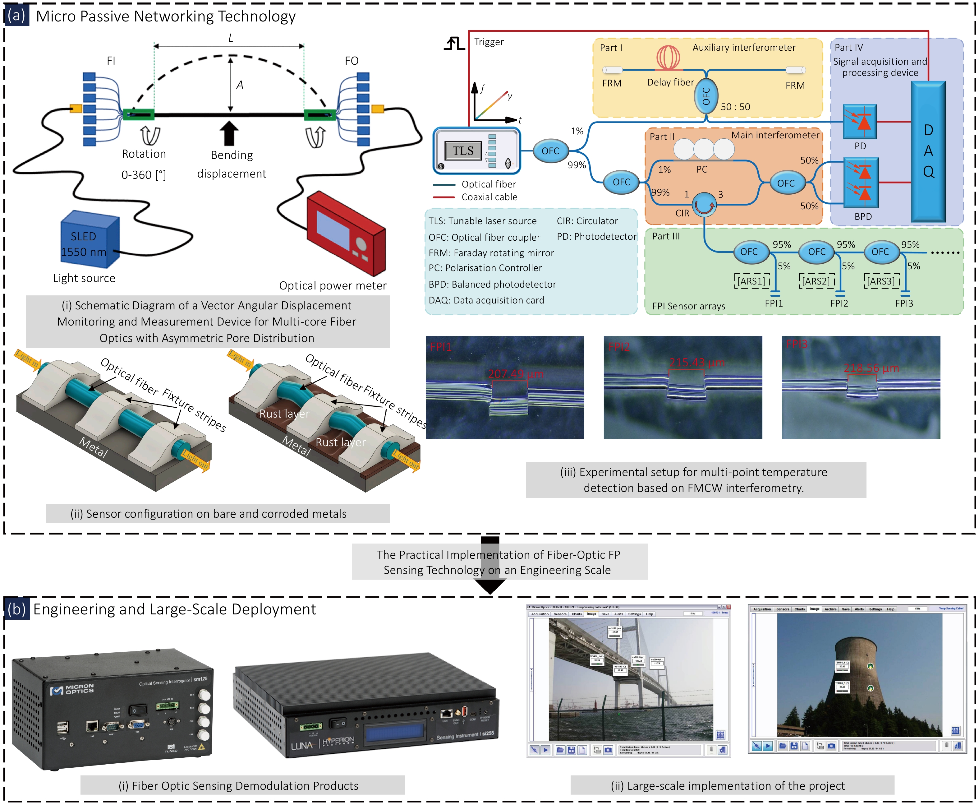
Figure 13. Engineering-scale development of fiber-optic F–P sensing technology. (a) Miniaturized networking technology, (b) current products and engineering applications; (a)i multi-core fiber vector angular displacement monitoring, (a)ii sensor applied to metal corrosion, (a)iii multi-point temperature detection based on FMCW interferometry; (b)i fiber-optic sensing demodulation products, (b)ii F–P sensor applications in bridges and thermal power plants. Figure reproduced from: (a)i ref134, Nanomaterials; (a)ii ref134, Nanomaterials; (a)iii ref133, iScience.
(5) Engineering and large-scale applications
The key technologies for transitioning fiber-optic F-P sensing from the laboratory to engineering field applications are still in a critical development period. Mature equipment systems represented by the HYPERION si255 and sm125 interrogators and the ENLIGHT software have formed a well-established ecosystem: the si255 supports 16 channels, a scan rate of 5000 Hz, and a bandwidth of 160 nm, capable of simultaneously measuring nearly a thousand sensors, meeting high-dynamic requirements such as aerospace wind tunnel testing; the sm125 is based on a tunable F–P filter and serves long-term static monitoring of bridges, dams, oil wells, etc., with a compact modular design—over half of the fiber optic sensors worldwide adopt this series; ENLIGHT provides an integrated platform from configuration and data acquisition to analysis and alarm archiving, compatible with multi-language APIs such as Python and MATLAB. These equipment systems have been applied to major projects such as rock mass monitoring at Mount Rushmore in the United States, oil and gas pipelines, offshore platforms, aircraft composite material testing, and temperature measurement of power switchgear, strongly supporting the development of industry standards from the product level to the system level135,136.
In industrial applications, fiber-optic F–P sensors have been successfully deployed for continuous pressure monitoring in oil and gas wells. Their high-temperature, high-pressure reliability is ensured by a metal–quartz tube mechanical pressure seal combined with a laser-based, adhesive-free hot-melt sealing technique137. In aero-engine dynamic strain measurement, the F–P system based on phase-tracking demodulation achieves a sensitivity of 100.955 pm/με (approximately 100 times that of an FBG), and a dynamic response frequency of 10 kHz138.
Silicon photonic integrated demodulation schemes, such as AWG and MZI, have demonstrated picometer-level accuracy in FBG interrogation, offering a promising reference for chip-scale demodulation of F-P systems139,140. Equipped with an embedded AI/ML engine, the VIAVI FTH-DAS interrogator enables real-time event classification and true physical quantity measurement, effectively transforming the device from a mere data acquisition unit into an intelligent terminal141.
Although miniaturization, integration, and intelligent sensing represent important development directions for F–P sensing systems, their large-scale industrial deployment continues to face challenges in long-term reliability, manufacturing consistency, and standardized evaluation. In extreme environments, long-term drift and repeated temperature-pressure cycling may compromise measurement stability, while fabrication tolerances in miniature F–P cavities and packaging structures can lead to significant device-to-device performance variations. Moreover, on-chip and intelligent demodulation schemes still require careful trade-offs among resolution, bandwidth, computational resources, model generalization, and cost. Therefore, long-term reliability, batch-to-batch consistency, and system-level engineering capability remain the key issues to be resolved for the industrialization of F–P sensing technologies.
7 Conclusion
Fiber-optic F–P sensors, by virtue of their high sensitivity, immunity to electromagnetic interference, resistance to high temperature and corrosion, ease of miniaturization, and long-distance transmission capability, have become an important technological approach for intelligent sensing in extreme environments. They are evolving from single-parameter measurement toward multi-parameter collaborative sensing systems. Structurally, F–P sensors are transitioning from simple interference cavities toward miniaturized, chip-based, and integrated designs. Technologies such as femtosecond laser processing, MEMS micromachining, and 3D micro-printing enable the direct fabrication of complex micro-structured sensitive units on fiber end faces, achieving highly sensitive detection of micro-force, displacement, vibration, and acoustics. New materials such as sapphire and hollow-core fibers further expand the measurement range for high temperature, high pressure, gas, humidity, and magnetic fields. Moreover, composite cavities and cascaded F–P/FBG structures endow sensors with multi-parameter synchronous measurement capability and in-situ temperature compensation, thereby promoting their engineering applications.
In terms of demodulation, three major technical routes have been established: intensity-based, phase-based, and spectral-based methods. For intensity demodulation, harmonic amplitude ratio, dual-wavelength ratio, and active feedback locking have improved demodulation stability. Phase demodulation techniques, including phase-generated carrier (PGC), multi-wavelength quadrature phase shift, and non-scanning correlation demodulation have achieved high-resolution, wide-dynamic-range detection. Broadband spectral demodulation methods, such as FFT, cross-correlation, and spectral comparison have improved absolute cavity length accuracy and composite cavity decoupling capability. Furthermore, artificial intelligence and deep learning, by leveraging neural networks to establish nonlinear mapping from spectra to physical quantities, provide a new approach for adaptive demodulation.
In terms of performance, sensors have achieved nm-level displacement detection and mPa-level acoustic pressure detection. Some sapphire MEMS structures can achieve ultra-high-temperature pressure measurement up to 1500 °C and high-pressure monitoring up to 100 MPa, with dynamic response capability reaching the kHz to MHz level. However, challenges remain regarding long-term stability, packaging thermal mismatch, material reliability, and multi-physics cross-coupling.
In practical applications, F–P sensors have been deployed in engineering scenarios such as aero-engines, gas turbines, nuclear power, deep sea, oil and gas, liquid metals, and intense radiation fields. By virtue of all-metal packaging, sapphire structures, and non-electrical measurement characteristics, they demonstrate advantages that conventional electrical sensors cannot easily replace. They also show promising potential in emerging directions including ultrasonic detection, photoacoustic imaging, gas photothermal detection, and miniaturized biomedical sensing.
Future development focuses on the following aspects: (1) Improving reliability and long-term stability in extreme environments through sapphire fibers, hollow-core fibers, ceramics, and all-metal packaging to enhance environmental adaptability. (2) Developing multi-cavity, multi-modal sensitive units and AI-assisted decoupling algorithms, combined with digital twins, to achieve real-time decoupling and intelligent compensation of multi-physical quantities. (3) Promoting the integration of MEMS, on-chip spectrometers, and integrated photonic chips to construct miniaturized intelligent sensing nodes integrating light source, interference cavity, demodulation, and wireless communication. (4) Leveraging FPGA, high-speed DAQ, and edge AI to achieve high-speed real-time demodulation and online anomaly diagnosis. (5) Establishing standardized testing, modular packaging, and reliability verification systems to promote large-scale applications in nuclear industry, aerospace, energy equipment, intelligent manufacturing, and other fields.
Overall, fiber-optic F–P sensing technology is transforming from high-sensitivity laboratory devices toward intelligent sensing systems for complex environments. It is expected to play a key role in extreme environment monitoring, major equipment health management, and intelligent perception networks, thereby becoming an important development direction for a new generation of high-end sensing technologies.
Competing interests
The authors declare no competing interests.
Article History
Received Date: 2026-05-28
Accepted Date: 2026-09-04
Available Online: 2026-09-28
Corresponding Author
Jie Zhang, zhangjie@cqu.edu.cn
Issue Info: Vol. 1, No. 1, 260004-1–260004-31
Citation
Wang N, Kang W, Tan J et al. Fiber-optic Fabry–Perot sensors and their demodulation techniques for extreme environment monitoring. Technology 1, 260004 (2026)
Author Information
Ning Wang
The Key Laboratory of Optoelectronic Technology & System, Education Ministry of China, Chongqing University, Chongqing 400044, China
Weijian Kang
The Key Laboratory of Optoelectronic Technology & System, Education Ministry of China, Chongqing University, Chongqing 400044, China
Jiahang Tan
The Key Laboratory of Optoelectronic Technology & System, Education Ministry of China, Chongqing University, Chongqing 400044, China
Feng Qin
The Key Laboratory of Optoelectronic Technology & System, Education Ministry of China, Chongqing University, Chongqing 400044, China
Yong Zhu
The Key Laboratory of Optoelectronic Technology & System, Education Ministry of China, Chongqing University, Chongqing 400044, China
Corresponding author Jie Zhang, E-mail: zhangjie@cqu.edu.cn
The Key Laboratory of Optoelectronic Technology & System, Education Ministry of China, Chongqing University, Chongqing 400044, China
Copyright & License
© The Author(s) 2026. Published by Technology Publishing.
Open Access This article is licensed under a Creative Commons Attribution 4.0 International License, which permits use, sharing, adaptation, distribution and reproduction in any medium or format, as long as you give appropriate credit to the original author(s) and the source, provide a link to the Creative Commons license, and indicate if changes were made. To view a copy of this license, visit http://creativecommons.org/licenses/by/4.0/
References
1. Liu Q, Wang Y, Zhao FJ et al. A review of the research progress of sensor monitoring technology in harsh engineering environments. Sensors 25, 6308 (2025). DOI: 10.3390/s25206308
2. Meena JS, Xiang LLY, Kannan DD et al. Extreme-temperature resistant, flexible, and sensitive strain sensor for aerospace parachute deployment. Adv Mater Technol 11, e02467 (2026). DOI: 10.1002/admt.202502467
3. Jahanshahi H, Zhu ZH. A comprehensive review of tactile sensing technologies in space robotics. Chin J Aeronaut 38, 103423 (2025). DOI: 10.1016/j.cja.2025.103423
4. Liu YH, Wang JL, Liu T et al. Triboelectric tactile sensor for pressure and temperature sensing in high-temperature applications. Nat Commun 16, 383 (2025). DOI: 10.1038/s41467-024-55771-0
5. Chen HC, Kuo CW, Chang TC et al. Investigation of the capacitance-voltage electrical characteristics of thin-film transistors caused by hydrogen diffusion under negative bias stress in a moist environment. ACS Appl Mater Interfaces 11, 40196–40203 (2019). DOI: 10.1021/acsami.9b11637
6. Taniker S, Costanza V, Celli P et al. Capacitive temperature sensing via displacement amplification. IEEE Sens J 22, 10388–10395 (2022). DOI: 10.1109/JSEN.2022.3169585
7. Hu YJ, Huang YP, Yang ZQ et al. Optimization of optical fiber monitoring technology and its rock pressure early warning mechanism in deep mining development environments. Eng Res Express 8, 035115 (2026). DOI: 10.1088/2631-8695/ae429c
8. Wang PJ, Pan YF, Zhang JS et al. Miniaturized and highly sensitive fiber-optic Fabry-Perot sensor for mHz infrasound detection. Photonics Res 12, 969–978 (2024). DOI: 10.1364/PRJ.519946
9. De Pauw B, Lamberti A, Ertveldt J et al. Vibration monitoring using fiber optic sensors in a lead-bismuth eutectic cooled nuclear fuel assembly. Sensors 16, 571 (2016). DOI: 10.3390/s16040571
10. Wang YJ, Liu J, Yang N et al. Fabrication of waveguide Bragg gratings on sapphire chip and their temperature sensing characteristics. Chin J Lasers 52, 1202403 (2025). DOI: 10.3788/CJL250466
11. Zhang XP, Zhang YX, Wang LA et al. Current status and future of research and applications for distributed fiber optic sensing technology. Acta Opt Sin 44, 0106001 (2024). DOI: 10.3788/AOS231473
12. Wang N, Zhu Y, Zhang J. Research status of fiber Fabry-Perot sensing technology under high temperature and high pressure environment. Laser Optoelectron Prog 60, 1106005 (2023). DOI: 10.3788/LOP230722
13. Li TL, Wu DJ, Khyam MO et al. Recent advances and tendencies regarding fiber optic sensors for deformation measurement: a review. IEEE Sens J 22, 2962–2973 (2022). DOI: 10.1109/JSEN.2021.3138091
14. Kumar V, Raghuwanshi SK, Kumar S. Advances in SPR-based fiber optic sensors for voltage/electric field measurement - A review. IEEE Sens J 24, 11986–11997 (2024). DOI: 10.1109/JSEN.2024.3373389
15. Zhou CX, Jia ZK, Song SB et al. Application of FBG sensor in health monitoring of engineering building structure: a review. Sens Rev 45, 129–145 (2025). DOI: 10.1108/SR-06-2024-0572
16. Wang M, Dai SX, Zhang PQ et al. Research progress on evanescent wave sensor based on mid-infrared optical fiber. J Chin Ceram Soc 50, 1117–1131 (2022). DOI: 10.14062/j.issn.0454-5648.20211175
17. Yu SJ, Cao K, Cao JJ et al. Portable SPR sensor with laser interference lithography – Fabricated Ag nanogratings for high-sensitivity biosensing. Sens Actuators A Phys 399, 117399 (2026). DOI: 10.1016/j.sna.2025.117399
18. Tong RJ, Zhao KJ, Xing B et al. An optical fiber sensor for salinity and temperature simultaneous detection based on dual SPR effect. Opt Laser Technol 175, 110760 (2024). DOI: 10.1016/j.optlastec.2024.110760
19. Zhang WJ, Su D, Qiao XG. High-temperature and high-pressure sensor based on sensitivity-enhanced suspended all-optical fiber Fabry-Pérot interferometer for downhole oil applications. IEEE Trans Instrum Meas 74, 9518709 (2025). DOI: 10.1109/TIM.2025.3562996
20. Hu Y, Wei HM, Ma ZW et al. Microbubble-based optical fiber Fabry-Perot sensor for simultaneous high-pressure and high-temperature sensing. Opt Express 30, 33639–33651 (2022). DOI: 10.1364/OE.465315
21. Islam MR, Ali MM, Lai MH et al. Chronology of Fabry-Perot interferometer fiber-optic sensors and their applications: a review. Sensors 14, 7451–7488 (2014). DOI: 10.3390/s140407451
22. Huang YW, Tao J, Huang XG. Research progress on F-P interference-based fiber-optic sensors. Sensors 16, 1424 (2016). DOI: 10.3390/s16091424
23. Cao XN, Yang H, Wu ZL et al. Ultrasound sensing with optical microcavities. Light Sci Appl 13, 159 (2024). DOI: 10.1038/s41377-024-01480-8
24. Huynh NT, Zhang E, Francies O et al. A fast all-optical 3D photoacoustic scanner for clinical vascular imaging. Nat Biomed Eng 9, 638–655 (2025). DOI: 10.1038/s41551-024-01247-x
25. Zhang L, Shang XG, Cao SM et al. Optical steelyard: high-resolution and wide-range refractive index sensing by synergizing Fabry–Perot interferometer with metafibers. PhotoniX 5, 24 (2024). DOI: 10.1186/s43074-024-00138-3
26. Xu YF, Teng HB, Zhao XY et al. Fiber-tip Fabry-Perot interferometric photothermal flexible gas sensor with capillary microcavity. ACS Sens 11, 3986–3992 (2026). DOI: 10.1021/acssensors.6c00294
27. Li CX, Liu YQ, Han DD et al. A tactile gripper on an optical fiber for perception and actuation. Nat Commun 16, 11513 (2025). DOI: 10.1038/s41467-025-66575-1
28. Fan XH, Li LY, Li ZJ et al. Monolithic 3D micro-encapsulation on optical fiber tips via femtosecond laser direct writing. Int J Extrem Manuf 8, 045004 (2026). DOI: 10.1088/2631-7990/ae4e6f
29. Lu QB, Wang YA, Wang XX et al. Review of micromachined optical accelerometers: from mg to sub-μg. Opto-Electron Adv 4, 200045 (2021). DOI: 10.29026/oea.2021.200045
30. Zhao MH, Qi YH, Wang HL et al. Optical interferometric MEMS accelerometers. Laser Photonics Rev 18, 2300713 (2024). DOI: 10.1002/lpor.202300713
31. Wang YH, Chen BT, Wu GR et al. Fiber-optic pressure sensors: recent advances in sensing mechanisms, fabrication technologies, and multidisciplinary applications. Sensors 25, 6336 (2025). DOI: 10.3390/s25206336
32. Chen Y, Lu DQ, Xing H et al. Recent progress in MEMS fiber-optic Fabry-Perot pressure sensors. Sensors 24, 1079 (2024). DOI: 10.3390/s24041079
33. Li TL, Zhang J, Al-Hadad M et al. Recent progress in fiber-optic acoustic sensor and its applications: a review. IEEE Sens J 24, 25249–25260 (2024). DOI: 10.1109/JSEN.2024.3422186
34. Shang XG, Wang N, Cao SM et al. Fiber-integrated force sensor using 3D printed spring-composed Fabry-Perot cavities with a high precision down to tens of piconewton. Adv Mater 36, 2305121 (2024). DOI: 10.1002/adma.202305121
35. Li TY, Liu Y, Xu WJ et al. Light control of a movable microbubble in an ethanol-filled fiber microcavity for displacement measurement. Opt Lett 49, 790–793 (2024). DOI: 10.1364/OL.510306
36. Cao SJ, Bai JD, Zheng YQ et al. High-temperature fiber-optic vibration sensor based on an atomic frequency standard. ACS Photonics 11, 3713–3721 (2024). DOI: 10.1021/acsphotonics.4c00885
37. Wang P, Li TG, Lin H et al. Miniature optical fiber accelerometer based on an in-situ 3D microprinted ferrule-top Fabry-Pérot microinterferometer. Light Adv Manuf 6, 152–160 (2025). DOI: 10.37188/lam.2025.018
38. Zhen YQ, Tu XT, Zhu JJ et al. Atomically smooth gold microflake-enabled fiber-tip Fabry–Perot interferometer for temperature and pressure sensing. ACS Appl Mater Interfaces 15, 35161–35169 (2023). DOI: 10.1021/acsami.3c04809
39. Liao YK, Liu J, Dai YT et al. Temperature-compensated fiber-optic Fabry-Perot pressure sensor based on sapphire MEMS technology for high temperature environment up to 1500°C. Opt Express 33, 19453–19463 (2025). DOI: 10.1364/OE.560263
40. Wei T, Zhang YQ, Zhang LQ et al. Research on ultra-high sensitivity fiber-optic cascaded Fabry-Perot resonator optical sensor based on the comb-spectrum vernier effect. J Lightwave Technol 42, 6182–6187 (2024). DOI: 10.1109/JLT.2024.3404783
41. Shen YF, Jiang Y, Xie SR et al. Cascaded Fabry-Perot cavity and fiber Bragg grating on sapphire fibers for high-temperature strain sensing. Opt Lasers Eng 184, 108674 (2025). DOI: 10.1016/j.optlaseng.2024.108674
42. Wang AQ, Fan XH, Chen G et al. Ultrahigh-sensitivity 3D-printed hollow Fabry-Pérot fiber ultrasound sensor for photoacoustic imaging. ACS Photonics 12, 4553–4562 (2025). DOI: 10.1021/acsphotonics.5c00944
43. Zhao PC, Krishnaiah KV, Guo LH et al. Ultraminiature optical fiber-tip 3D-microprinted photothermal interferometric gas sensors. Laser Photonics Rev 18, 2301285 (2024). DOI: 10.1002/lpor.202301285
44. Zhao ZK, Qian CW, Ni WJ et al. Microscale intrinsic fiber mode vernier photothermal spectroscopy gas sensing. Laser Photonics Rev 20, e02114 (2026). DOI: 10.1002/lpor.202502114
45. Xiong C, Wang CY, Yu RW et al. 3D printed multicore fiber-tip discriminative sensor for magnetic field and temperature measurements. Light Adv Manuf 5, 84–94 (2024). DOI: 10.37188/lam.2024.018
46. Chen MQ, Liu SY, Zhang C et al. Two-photon 3D printing FP microcavity sensor for simultaneous measurement of temperature and non-contact pressure. Opt Laser Technol 179, 111406 (2024). DOI: 10.1016/j.optlastec.2024.111406
47. Li WT, Li C, Wan Z et al. Photothermally actuated Ti3C2Tx MXene-GO resonator for highly sensitive humidity sensing. Sens Actuators B Chem 461, 139983 (2026). DOI: 10.1016/j.snb.2026.139983
48. Qin F, Zheng TT, Tan JH et al. Design and experiment of high temperature Fabry-Perot acceleration sensor with composite cavity. Opt Precis Eng 32, 3174–3183 (2024). DOI: 10.37188/OPE.20243221.3174
49. Zhu C, Gerald RE, Huang J. Progress toward sapphire optical fiber sensors for high-temperature applications. IEEE Trans Instrum Meas 69, 8639–8655 (2020). DOI: 10.1109/TIM.2020.3024462
50. Deng YQ, Jiang J. Optical fiber sensors in extreme temperature and radiation environments: a review. IEEE Sens J 22, 13811–13834 (2022). DOI: 10.1109/JSEN.2022.3181949
51. Ma SN, Xu YP, Pang YX et al. Optical fiber sensors for high-temperature monitoring: a review. Sensors 22, 5722 (2022). DOI: 10.3390/s22155722
52. Huang PJ, Wang N, Li JY et al. Fiber Fabry-Perot force sensor with small volume and high performance for assessing fretting damage of steam generator tubes. Sensors 17, 2899 (2017). DOI: 10.3390/s17122899
53. Lin C, Wang N, Chen JJ et al. Study on fiber Fabry–Perot displacement sensor for vibration monitoring of fuel pin. Microw Opt Technol Lett 66, e34007 (2024). DOI: 10.1002/mop.34007
54. Jiao JA, Chen JJ, Wang N et al. Study of a fiber optic Fabry-Perot strain sensor for fuel assembly strain detection. Sensors 22, 9097 (2022). DOI: 10.3390/s22239097
55. Liu LL, Qin F, Xu YG et al. All-metal packaged temperature compensation fiber optic Fabry-Pérot strain sensor for high-temperature liquid metal environments. Measurement 256, 118501 (2025). DOI: 10.1016/j.measurement.2025.118501
56. Tan JH, Qin F, Wang N et al. Dual-function composite optical fiber Fabry–Pérot sensor and its demodulation system for simultaneous high-precision measurement of pressure and temperature. IEEE Trans Instrum Meas 74, 9537007 (2025). DOI: 10.1109/TIM.2025.3615309
57. Tan JH, Qin F, Wang N et al. All-sapphire-based high-temperature pressure sensor system with in situ temperature compensation: innovative cavity design, fabrication, and APSC-FFT algorithm. Microsyst Nanoeng 12, 159 (2026). DOI: 10.1038/s41378-026-01290-5
58. Qin F, Tan JH, Guo JT et al. Fiber-optic Fabry-Pérot interferometric accelerometer with composite cavity and temperature calibration for high-temperature and high-pressure applications. Microsyst Nanoeng 12, 155 (2026). DOI: 10.1038/s41378-026-01250-z
59. Li ZR, Dang WJ, Dan JX et al. High-sensitivity interferometric high-temperature strain sensor based on optical harmonic vernier effect. Opt Fiber Technol 79, 103361 (2023). DOI: 10.1016/j.yofte.2023.103361
60. Zhao XN, Wu XQ, Zuo C et al. Miniatured Fabry-Perot strain probe based on anti-resonant hollow core fiber. Measurement 203, 111775 (2022). DOI: 10.1016/j.measurement.2022.111775
61. Wang X, Jiang JF, Wang S et al. All-silicon dual-cavity fiber-optic pressure sensor with ultralow pressure-temperature cross-sensitivity and wide working temperature range. Photonics Res 9, 521–529 (2021). DOI: 10.1364/PRJ.414121
62. Zhang YT, Jiang Y, Yang SW et al. All-sapphire fiber-optic sensor for the simultaneous measurement of ultra-high temperature and high pressure. Opt Express 32, 14826–14836 (2024). DOI: 10.1364/OE.519656
63. Cui Y, Jiang Y, Zhang YT et al. Sapphire optical fiber high-temperature vibration sensor. Opt Express 30, 1056–1065 (2022). DOI: 10.1364/OE.447449
64. Qiu ZJ, Zhang GQ, Zhang M et al. Research on a signal demodulation algorithm for fiber optic acoustic sensors based on the amplitude ratio of harmonic components. Opt Express 32, 42274–42288 (2024). DOI: 10.1364/OE.537932
65. Yoshino T, Kurosawa K, Itoh K et al. Fiber-optic Fabry-Perot interferometer and its sensor applications. IEEE Trans Microw Theory Tech 30, 1612–1621 (1982). DOI: 10.1109/TMTT.1982.1131298
66. Miao YZ, Xue F, Li MW et al. Spectrum contrast enhancement of fiber Fabry-Perot sensor by coupling efficiency improvement. Opt Commun 573, 131015 (2024). DOI: 10.1016/j.optcom.2024.131015
67. Dandridge A, Tveten A, Giallorenzi T. Homodyne demodulation scheme for fiber optic sensors using phase generated carrier. IEEE J Quantum Electron 18, 1647–1653 (1982). DOI: 10.1109/JQE.1982.1071416
68. Li Q, Shao J, Wu P et al. Research on high-precision PGC demodulation method for Fabry-Perot sensors based on shifted sampling pre-calibration. Sensors 25, 5990 (2025). DOI: 10.3390/s25195990
69. Chen YC, Taylor HF. Multiplexed fiber Fabry–Perot temperature sensor system using white-light interferometry. Opt Lett 27, 903–905 (2002). DOI: 10.1364/OL.27.000903
70. Xu YF, Qi HC, Zhao XY et al. High-speed spectrum demodulation of fiber-optic Fabry–Perot sensor based on scanning laser. Opt Lasers Eng 178, 108192 (2024). DOI: 10.1016/j.optlaseng.2024.108192
71. Li WC, Yuan YG, Yang J et al. Review of optical fiber sensor network technology based on white light interferometry. Photonic Sens 11, 31–44 (2021). DOI: 10.1007/s13320-021-0613-x
72. Pan Z, Liu HJ, Wang LX et al. Draw-tower-grating-based Fabry-Perot interferometers for simultaneous measurements of temperature and salinity. Opt Express 32, 22687–22699 (2024). DOI: 10.1364/OE.523935
73. Zhu ZD, Ba DX, Liu L et al. Temperature-compensated multi-point refractive index sensing based on a cascaded Fabry-Perot cavity and FMCW interferometry. Opt Express 29, 19034–19048 (2021). DOI: 10.1364/OE.424995
74. Chen YF, Wang TH, Yang PC et al. Optical Vernier effect-based demodulation system for fiber-optic sensors: an AWG and a neural network-based perspective. Appl Opt 64, 6077–6084 (2025). DOI: 10.1364/AO.563160
75. Ren SF, Chen SC, Hu YL et al. Rethink training: synthetic data powers efficient fiber-optics sensor demodulation neural networks. IEEE Sens J 24, 31408–31416 (2024). DOI: 10.1109/JSEN.2024.3441239
76. Wang L, Zhou R, Li M et al. Asymmetric reflection spectrum of Fabry-Perot interferometer and the application in pressure sensing. J Lightwave Technol 40, 4011–4019 (2022). DOI: 10.1109/JLT.2022.3153517
77. Zuo Y, Li C, Zhao Y et al. A dual-wavelength demodulation-based sensor for magnetic fields. Sens Actuators A Phys 366, 114959 (2024). DOI: 10.1016/j.sna.2023.114959
78. Li ZX, Wan SP, Yu JS. Research on real-time gear fault detection and classification technology based on EFPI vibration sensor. Opt Laser Technol 192, 113627 (2025). DOI: 10.1016/j.optlastec.2025.113627
79. Ye W, Ren QY, Wang HR et al. High-stability quadrature-point demodulation technique for dynamic interrogation of fiber Fabry–Perot sensors. Appl Opt 65, 1427–1436 (2026). DOI: 10.1364/AO.585838
80. Wang F, Guo XH, Yuan YZ et al. Temperature monitoring system for fiber optic multichannel applications based on double-cone microstructure and ceramic-inserted F-P cavities. Opt Laser Technol 198, 114913 (2026). DOI: 10.1016/j.optlastec.2026.114913
81. Zhang SH, Zhang LQ, He C et al. Improved PGC-Arctan demodulation scheme with immunity to carrier phase delay and modulation depth. Opt Lasers Eng 176, 108072 (2024). DOI: 10.1016/j.optlaseng.2024.108072
82. Liu Y, Qi B, Winder DE. Faraday Michelson interferometers for signal demodulation of fiber-optic sensors. J Lightwave Technol 39, 2552–2558 (2021). DOI: 10.1109/JLT.2021.3053370
83. Zhang WJ, Lu P, Qu ZY et al. Four-wavelength quadrature phase demodulation technique for extrinsic Fabry–Perot interferometric sensors. Opt Lett 47, 2406–2409 (2022). DOI: 10.1364/OL.460132
84. Shi JH, Guang D, Li SL et al. Single-wavelength passive phase-shifted demodulation technique with the dual-cavity and EFA for the interrogation of EFPI diaphragm-based fiber sensor. J Lightwave Technol 40, 222–227 (2022). DOI: 10.1109/JLT.2021.3069033
85. Huang Y, Chen HW, Zhang LN et al. Improved dual-wavelength demodulation technique based on prior information for fiber optic Fabry-Pérot ultrasonic sensors. J Lightwave Technol 42, 6444–6450 (2024). DOI: 10.1109/JLT.2024.3416989
86. Zhang SH, Dong JY, Peng M et al. Fiber-optic extrinsic Fabry–Perot interferometer sensors with quadrature phase three wavelength demodulation. Eur Phys J Plus 139, 1005 (2024). DOI: 10.1140/epjp/s13360-024-05809-5
87. Lee CE, Taylor HF. Fiber-optic Fabry-Perot temperature sensor using a low-coherence light source. J Lightwave Technol 9, 129–134 (1991). DOI: 10.1109/50.64932
88. Guo ZL, Lv WT, Wang W et al. Absolute single cavity length interrogation of fiber-optic compound Fabry–Perot pressure sensors through a white light non-scanning correlation method. Sensors 19, 1628 (2019). DOI: 10.3390/s19071628
89. Tan JH, Wang Q, Wang N et al. Hardware optical correlation method for dynamic detection of micrometer gaps with sub-nanometer resolution. Opt Express 30, 32660–32669 (2022). DOI: 10.1364/OE.464475
90. Kong DY, Song ZY, Wang N et al. Fiber Fabry-Perot demodulation system based on dual Fizeau interferometers. Photonic Sens 13, 230229 (2023). DOI: 10.1007/s13320-022-0670-9
91. Chen HB, Zhang Y, Li Y et al. Squared peak-to-peak algorithm for the spectral interrogation of short-cavity fiber-optic Fabry–Perot sensors. Appl Opt 59, 1198–1205 (2020). DOI: 10.1364/AO.382169
92. Jiang Y. High-resolution interrogation technique for fiber optic extrinsic Fabry-Perot interferometric sensors by the peak-to-peak method. Appl Opt 47, 925–932 (2008). DOI: 10.1364/AO.47.000925
93. Mei JW, Xiao XS, Yang CX. High-resolution and large dynamic range fiber extrinsic Fabry–Perot sensing by multi-extrema-tracing technique. Appl Opt 54, 3677–3681 (2015). DOI: 10.1364/AO.54.003677
94. Hai ZY, Su ZX, Liang R et al. Numerical and experiment analysis of sapphire sandwich-structure Fabry–Perot pressure sensor through fast Fourier transform and mean square error demodulation algorithm. Materials 17, 3649 (2024). DOI: 10.3390/ma17153649
95. Shao ZQ, Wu YL, Sun ZQ et al. Excellent repeatability, all-sapphire Fabry Perot optical pressure sensor based on wet etching and direct bonding for harsh environment applications. Opt Express 29, 19831–19838 (2021). DOI: 10.1364/OE.423753
96. Li CX, Qi HC, Han X et al. Ultrahigh-speed phase demodulation of a Fabry–Perot sensor based on fiber array parallel spectral detection. Opt Lett 49, 714–717 (2024). DOI: 10.1364/OL.511903
97. Shin DW, Matsukuma H, Sato R et al. Improved peak-to-peak method for cavity length measurement of a Fabry-Perot etalon using a mode-locked femtosecond laser. Opt Express 31, 25797–25814 (2023). DOI: 10.1364/OE.493507
98. Zhang T, Han Q, Ma QY et al. Intensity demodulation of optical vernier effect: an intelligent algorithm approach. IEEE Sens J 24, 10084–10090 (2024). DOI: 10.1109/JSEN.2024.3363019
99. Li JW, Gao MQ, Li JL et al. High accuracy sitting posture monitoring enabled by multiplexing fiber optic microsphere array and deep learning. Measurement 268, 120710 (2026). DOI: 10.1016/j.measurement.2026.120710
100. Li YC, Liu B, Xiao S et al. Dual-parametric demodulation of temperature and pressure for EFPI-FBG sensors based on deep learning methods. Opt Lasers Eng 198, 109482 (2026). DOI: 10.1016/j.optlaseng.2025.109482
101. Liu J, Qian J, Zhao QR et al. All-silica optical fiber Fabry-Perot vibration sensor based on MEMS and laser welding for high temperature up to 800 °C. Sens Actuators A Phys 399, 117497 (2026). DOI: 10.1016/j.sna.2026.117497
102. Li YH, Wang J, Sun YN et al. Fiber-optic Fabry-Perot sensor based on spectral quality-enhanced microsphere lens for high-temperature strain measurement. Opt Express 34, 5982–5996 (2026). DOI: 10.1364/OE.582907
103. Zhu YM, Zhou JM, Jin T et al. High-temperature-resistant gas pressure sensor based on an all-silica Fabry-Perot interferometer. Appl Opt 64, 5688–5697 (2025). DOI: 10.1364/AO.565014
104. He X, He ZX, Ran ZL et al. Temperature-insensitive Quasi-distributed Fiber-optic Fabry-Perot high-pressure sensing based on microwave interference system. Opt Laser Technol 161, 109069 (2023). DOI: 10.1016/j.optlastec.2022.109069
105. He X, Ran ZL, Ding ZY et al. Fast-response sensitivity-enhanced all-fiber Fabry-Pérot high-pressure sensor for internal combustion engines. J Lightwave Technol 40, 299–307 (2022). DOI: 10.1109/JLT.2021.3119410
106. Dai GH, Su D, Qiao XG. Sensitivity-enhanced high-pressure sensor based on suspended fiber-optic Fabry-Pérot interferometer. IEEE Trans Instrum Meas 71, 7008507 (2022). DOI: 10.1109/TIM.2022.3217847
107. Zhao SS, Sun QQ, Yang SQ et al. High-resolution silicon-based optical Fabry-Perot sensing system for seawater temperature measurement. J Lightwave Technol 43, 10312–10321 (2025). DOI: 10.1109/JLT.2025.3608331
108. Wang EB, Niu HJ, Li P et al. Optical fiber F-P cavity pH sensor based on polyaniline reaction deposition film layer. Measurement 243, 116454 (2025). DOI: 10.1016/j.measurement.2024.116454
109. Yang HR, Xie S, Xin F et al. Ultra-sensitive F–P humidity sensor based on an open-cavity note-type structure for GIS low-humidity monitoring. IEEE Sens J 26, 13197–13204 (2026). DOI: 10.1109/JSEN.2026.3677260
110. Zhang JW, Wang L, Chen JH et al. An optical measurement method for nanosecond impulse signal monitoring of partial discharge based on the Fabry-Perot interferometer sensing system. Jpn J Appl Phys 61, 102006 (2022). DOI: 10.35848/1347-4065/ac88a9
111. Hossain MM, Pant TK, Vineeth C. Nocturnal thermospheric neutral wind and temperature measurement using a Fabry-Perot interferometer: first results from an equatorial Indian station. Adv Space Res 72, 598–613 (2023). DOI: 10.1016/j.asr.2023.03.040
112. Hwang J, Ku Z, Jeon J et al. Polarization-sensitive and wide incidence angle-insensitive Fabry–Perot optical cavity bounded by two metal grating layers. Sensors 20, 5382 (2020). DOI: 10.3390/s20185382
113. Pang XK, Yao GZ, Wang ZF et al. Sapphire MEMS fiber-optic sensor with a ceramic-housing package for high-temperature vibration. IEEE Photonics Technol Lett 38, 1231–1234 (2026). DOI: 10.1109/LPT.2026.3682756
114. Gao ZX, Du X, Li YY et al. MOF-based fiber-optic iodine vapor vernier sensor with temperature crosstalk reduction by TOC&TEC. Opt Fiber Technol 94, 104381 (2025). DOI: 10.1016/j.yofte.2025.104381
115. Zhang YT, Jiang Y, Cui Y et al. An all-fiber diaphragm-based extrinsic Fabry-Perot sensor for the measurement of pressure at ultra-low temperature. Meas Sci Technol 33, 055117 (2022). DOI: 10.1088/1361-6501/ac51f0
116. Li SL, Chen C, Zhao DL et al. A dynamic spectral demodulation scheme of the fiber optical Fabry-Perot sensor for low-frequency vibration detection. Opt Laser Technol 171, 110436 (2024). DOI: 10.1016/j.optlastec.2023.110436
117. Amoudry L, Wang H, Cassou K et al. Modal instability suppression in a high-average-power and high-finesse Fabry-Perot cavity. Appl Opt 59, 116–121 (2020). DOI: 10.1364/AO.59.000116
118. Xie BW, Zhang WJ, Zhao JM et al. VO2-based superposed Fabry-Perot multilayer film with a highly enhanced infrared emittance and emittance tunability for spacecraft thermal control. Opt Express 30, 34314–34327 (2022). DOI: 10.1364/OE.464266
119. Allam AM, Mahmoud AM, Boltia SA et al. Photonic sensor for selective Ticagrelor detection based on porous silicon Fabry-Pérot interferometer modified with molecularly imprinted co-polymer. Microchem J 214, 114007 (2025). DOI: 10.1016/j.microc.2025.114007
120. Chen H, Buric M, Ohodnicki PR et al. Review and perspective: sapphire optical fiber cladding development for harsh environment sensing. Appl Phys Rev 5, 011102 (2018). DOI: 10.1063/1.5010184
121. Ferreira MFS, Rehan M, Mishra V et al. Roadmap on specialty optical fibers. J Phys Photonics 7, 012501 (2025). DOI: 10.1088/2515-7647/ad6b19
122. Mondal A, El Aadad H, El Hamzaoui H et al. Highly stable 3D printed microsensors at optical fiber tips. Sens Actuators A Phys 390, 116620 (2025). DOI: 10.1016/j.sna.2025.116620
123. Liu J, Zhang L, Wang ZY et al. Extreme dual-parameter optical fiber sensor composed of MgO Fabry-Perot composite cavities for simultaneous measurement of temperature and pressure. Appl Sci 15, 8891 (2025). DOI: 10.3390/app15168891
124. Wang SX, Lei ZZ, Jiang YG. Research progress on ceramic-based high-temperature-resistant fiber-optic sensor technology. J Funct Mater Dev 32, 022102 (2026). DOI: 10.3724/jfmd.2507042
125. Chen XY, Kang X, Gan Y et al. High-resolution, broadband on-chip spectrometer with tunable multi-mode waveguide Bragg gratings. Opt Express 33, 35385–35399 (2025). DOI: 10.1364/OE.570103
126. Chen XY, Gan XT, Zhu Y et al. On-chip micro-ring resonator array spectrum detection system based on convex optimization algorithm. Nanophotonics 12, 715–724 (2023). DOI: 10.1515/nanoph-2022-0672
127. Zhang ZM, Xiao SM, Song QH et al. Scalable on-chip diffractive speckle spectrometer with high spectral channel density. Light Sci Appl 14, 130 (2025). DOI: 10.1038/s41377-025-01797-y
128. 128 Shojaei Khatouni S, Zakowski S, Hosseini Vedad R et al. Discriminating temperature, strain, and bending effects in fiber Bragg grating Fabry-Perot interferometer sensors using traditional machine learning techniques. V1. TechRxiv (2023-04-19)[2026-05-28]. https://doi.org/10.36227/techrxiv.22644031.v1.
129. Deng CF, Yu MX, Zhu LQ et al. A deep learning algorithm ADPNet for strain and temperature decoupling of fiber Bragg gratings. Opt Fiber Technol 79, 103356 (2023). DOI: 10.1016/j.yofte.2023.103356
130. Cao LD, Abedin S, Cui GQ et al. Artificial intelligence and machine learning in optical fiber sensors: a review. Sensors 25, 7442 (2025). DOI: 10.3390/s25247442
131. 131 Ren SF, Chen SC, Shi H et al. A generalizable wavelength demodulation method for fiber-optic Fabry-Pérot pressure sensors via federated learning. In <italic>Proceedings of the 23rd International Conference on Optical Communications and Networks</italic> 1–3 (IEEE, Zhangjiajie, 2025). https://doi.org/10.1109/ICOCN67308.2025.11145411.
132. Wei CH, Liu Q, Wang YP et al. Accurate strain sensing with fiber-optic Fabry-Perot sensors based on CNN-LSTM model. IEEE Sens J 24, 17725–17732 (2024). DOI: 10.1109/JSEN.2024.3386724
133. Mo CY, Yang YQ, Mu XG et al. Sensitive detection of multi-point temperature based on FMCW interferometry and DSP algorithm. Nanomaterials 15, 1545 (2025). DOI: 10.3390/nano15201545
134. Malinka F, Vachek O, Krizan D et al. Advanced intensity-modulated fiber sensors for scalable sensing. iScience 28, 113670 (2025). DOI: 10.1016/j.isci.2025.113670
135. 135 Micron Optics. ENLIGHT sensing analysis software. Available online: https://lunainc.com/sites/default/files/assets/files/resource-library/Micron-Optics-ENLIGHT-0902.b_0902.3.pdf (accessed on 2026-05-28).
136. 136 Micron Optics. sm125 Optical sensing interrogator. Available online: https://pdf.directindustry.com/pdf/micron-optics/sm125/101517-610145.html (accessed on 2026-05-28).
137. Yang B, Zhao QC, Che CR et al. High-precision optical fiber temperature and pressure sensor and its application in production wells. Laser Optoelectron Prog 59, 1706006 (2022). DOI: 10.3788/LOP202259.1706006
138. Liu Y, Wen ZX, Yang CX et al. A high-precision and high-frequency dynamic strain measurement system for aeroengine. Meas Control Technol 43, 63–69 (2024). DOI: 10.19708/j.ckjs.2023.11.261
139. Zhuang Y, Zou J, Zhang JQ et al. On-chip sub-picometer continuous wavelength fiber-Bragg-grating interrogator. Photonic Sens 14, 240126 (2024). DOI: 10.1007/s13320-023-0694-9
140. Marin YE, Nannipieri T, Oton CJ et al. Integrated FBG sensors interrogation using active phase demodulation on a silicon photonic platform. J Lightwave Technol 35, 3374–3379 (2017). DOI: 10.1109/JLT.2016.2598395
141. 141 VIAVI Solutions Inc. VIAVI launches industry-leading true-phase DAS fiber sensing interrogator with AI/ML at the edge to enable real-time infrastructure monitoring. Available online: https://newswire.telecomramblings.com/2026/03/viavi-launches-industry-leading-true-phase-das-fiber-sensing-interrogator-with-ai-ml-at-the-edge-to-enable-real-time-infrastructure-monitoring/ (accessed on 2026-05-28).